
Get in Touch with GUANGQI


LED pixel lights are individually addressable light points that form grids on building facades, bridges, sculptures, and signage. Unlike a conventional LED flood or strip — where every emitter shares one color at a time — each pixel in this category carries an integrated circuit, reads its own slice of a data stream, and sets its own color and brightness. In practice, a facade stops being a static colorwash and starts behaving as a low-resolution animated display. That category barely existed as a commercial product before roughly 2010.This guide walks through how addressable pixel lighting actually works at the data-stream level, how to calculate pixel pitch against viewing distance, the differences between DMX512 and SPI control, the driver IC landscape (WS2811, UCS1903, SM16703, APA102), power supply sizing and voltage drop engineering, pixel mapping software workflows, the installation mistakes that surface two years after commissioning, and the 2026 outlook around RDM and IP-based control. References at the end link the IEC 60529 IP code, ANSI E1.11 DMX512-A, and ANSI E1.20 RDM standards cited throughout.
Quick Specs: LED Pixel Lights
| Typical voltage | DC 12V / 24 V (48 V for long runs, 5 V for small indoor strings) |
| Power per pixel | 0.5 – 3.9 W |
| Outdoor IP rating | IP67 — dust-tight plus 1 m immersion for 30 min (IEC 60529) |
| Control protocols | DMX512 (ANSI E1.11), SPI, TTL |
| Common driver ICs | WS2811, UCS1903, SM16703, APA102 / SK9822 |
| Pixel pitch range | 50 – 200 mm (facade); 10 – 50 mm (close-viewing retail) |
| Operating temperature | −30 °C to +60 °C |
| Rated lifespan | 50,000 hours typical |
What Are LED Pixel Lights? Definition and How They Differ from Strip, Neon, and LED Video Walls

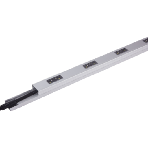
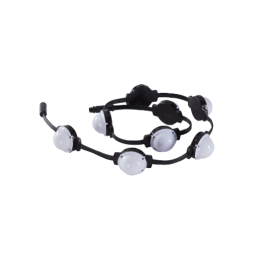
An LED pixel light is a single sealed light point with its own brains. Inside the housing sits an RGB or RGBW LED together with a small driver IC. That IC listens on a shared data line, reads the bytes at its own address, and drives the LED to a specific color and brightness. Put hundreds or thousands of these modules onto a facade grid, feed them from a pixel controller, and the wall becomes a low-resolution display.
Three adjacent product families look similar but solve different problems. An LED strip is a flexible tape with fixed LED spacing; basic strips color the entire length identically, while addressable variants (WS2812B RGB LED strips, for example) behave as linear pixel lights. Neon flex is an extruded silicone profile producing one continuous line of light, with no per-point control. Direct-view LED video walls use 1–10 mm pitches for indoor video at 2–10 m viewing distances — a different cost class and a different design problem from facade pixel lighting, which lives at 50–200 mm pitch and 30+ m viewing. Compact “mini” pixel variants with 10–20 mm bodies fit into signage and curtain-wall applications where larger 30+ mm modules would dominate the design visually.
| Attribute | LED Pixel Light | Addressable LED Strip | Neon Flex | LED Video Wall |
|---|---|---|---|---|
| Addressability | Per module | Per LED along strip | None (continuous) | Per pixel on panel |
| Typical pitch | 50 – 200 mm | 16 – 33 mm (fixed) | n/a | 1 – 10 mm |
| Outdoor rating | IP67 typical | IP65 – IP68 | IP65 – IP67 | IP65 outdoor grade |
| Power per unit | 0.5 – 3.9 W / pixel | 4 – 24 W / meter | 5 – 12 W / meter | 200 – 800 W / m² |
| Best use | Facade grids, 3D forms, media walls | Cove, contour, linear accent | Edge outlines, signage | Close-viewing video |
What Is the Difference Between an LED and a Pixel LED?
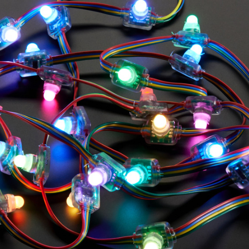
Generic LEDs are just diodes — constant voltage in, constant color out, no controller. Pixel LEDs package the same diode together with a driver IC that reads a serial data stream and responds only to bytes at its own address. Without the IC, a module is a static lamp; with it, the module behaves as one data point on a display.
Addressable LED is the broader umbrella term that covers pixel lights, addressable strips, and similar products — any LED where each emitter (or group of emitters) responds independently to a control signal. Pixel lights are the subset built as discrete mechanical modules, ready for mounting on a building surface.
How Addressable Pixel Lighting Works: The IC, the Data Stream, and the Pixel Map

Four things happen inside any working pixel installation. Content originates on a laptop, show controller, or media server as a sequence of color values — one per pixel per frame. Pixel controllers reformat that sequence into a serial data stream on either DMX512 or SPI. Inside each pixel, a driver IC reads the bytes at its assigned slot, writes the PWM signal that sets the LED color and brightness, then forwards remaining bytes to the next pixel in the chain.
Data streams are organized by byte slots. On DMX512, each universe carries 512 data slots; an RGB pixel consumes three slots (one per color channel), and an RGBW pixel consumes four. ESTA E1.11 defines how the master transmits a break, a mark-after-break, and the 513 bytes that follow (one start code plus 512 data slots). On SPI, the format is looser — each chip expects a specific bit rate and frame format defined by its own datasheet.
📐 Engineering Note: Refresh Rate vs PWM Rate
These two numbers get confused routinely. Refresh rate is how many times per second the controller updates the entire pixel chain — usually 30–60 Hz for animated content. PWM rate is how fast the driver IC toggles the LED to produce an intermediate brightness; for flicker-free video-grade output, aim for 2 kHz or higher. A WS2811 runs an 800 kbps data line with roughly 400 Hz PWM on standard variants, which is acceptable for direct viewing but visible on slow-motion camera footage. For event broadcast or close-camera work, specify ICs that publish higher PWM (SM16703 and newer parts advertise variants above 2 kHz).
An RGB LED sits on the output side of the IC, so a single RGB LED driven by a WS2811 or UCS1903 behaves as one addressable pixel. Modules stacking 3–4 RGB LED emitters into one housing share a single IC and appear as one brighter pixel from typical viewing distance.
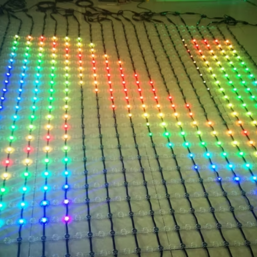
Pixel maps connect logical content to physical layout. Content software knows about a 100×50-pixel “canvas” of abstract color values. Its pixel map assigns each canvas coordinate to a physical pixel address — DMX universe 3, channel 127, for example. Once the map is built, any image or video the content software produces plays out across the facade with no further wiring change.
The pixel map abstraction is what makes content authoring tractable at scale.
Pixel Pitch and Density: The Viewing-Distance Math You Can Actually Use
Pixel pitch is the center-to-center distance between two adjacent pixels, measured in millimeters. Density is the count of pixels per square meter. These two are tightly linked: halving the pitch quadruples the density — and the cost.
One rule of thumb matters most for specification. Documented on r/VIDEOENGINEERING and built into calculators such as Brightlink’s LED display tool, it reads:
The 1:1 Rule — Minimum Viewing Distance
Minimum viewing distance (meters) ≈ Pixel pitch (millimeters)
A facade at 4.8 mm pitch becomes smooth at about 4.8 m. A 50 mm facade grid reads cleanly from 50 m. Multiply by three for the “comfortable” distance at which individual pixels disappear completely and the image looks solid.
That rule originates with direct-view LED video walls, but it transfers to facade pixel lighting with one caveat: facade content is usually abstract animation or color wash, not moving imagery with fine detail. Facades therefore tolerate coarser pitches than the rule would suggest for video. A 100 mm facade grid can display readable corporate logos from 50 m, even though the strict “video” minimum would be 100 m.
| Scenario | Viewing distance | Pitch | Density |
|---|---|---|---|
| Close-viewing retail facade | 5 – 10 m | 25 – 50 mm | 400 – 1,600 px/m² |
| Mid-rise commercial facade | 30 – 50 m | 100 – 150 mm | 44 – 100 px/m² |
| High-rise media facade | 50 – 100 m | 150 – 250 mm | 16 – 44 px/m² |
| Landmark / bridge | > 100 m | 200 – 400 mm | 6 – 25 px/m² |
To run the math for your own project, a pixel density calculator converts a facade area and a target viewing distance into a pixel count and a power estimate.
DMX512 vs SPI: Which Control Protocol Should You Use?

Every pixel installation lands on one of two control protocols — DMX512 or SPI — and that choice determines wiring cost, control-room workflow, and the ceiling on project size. ESTA E1.11 sets DMX512 at 512 channels per universe. Divide by 3 channels per RGB pixel, and one universe controls exactly 170 RGB pixels. For RGBW, divide 512 by 4 — 128 pixels per universe. Large projects run multiple universes in parallel via sACN (ANSI E1.31) or Art-Net over standard Ethernet.
SPI is less standardized. Each driver IC defines its own bit rate and frame format; practical chain length before signal degradation is usually 500 to 1,000 pixels per data line, depending on chip and cable quality. One forum post on r/lightingdesign captures the practitioner consensus bluntly: “Break up the data runs as much as your controller and console will allow.” Long unbroken SPI chains are the first thing to fail at scale.
| Feature | DMX512 (ANSI E1.11) | SPI |
|---|---|---|
| Standard body | ESTA / ANSI E1.11-2008 R2018 | Per-IC datasheet (de facto) |
| Channels / capacity | 512 per universe — 170 RGB or 128 RGBW pixels | Unlimited addresses; practical chain ~500–1000 pixels |
| Electrical | Differential RS-485, 5-pin XLR or RJ45 | Single-ended TTL clock + data |
| Cable distance | Up to 300 m per universe with termination | 5–20 m before buffering needed |
| IP extension | sACN (ANSI E1.31), Art-Net over Ethernet | None native; requires SPI-to-Ethernet converter |
| Typical cost | Higher per pixel (decoder IC + cabling) | Lower per pixel |
How Many LED Pixels Can One DMX Universe Control?
Exactly 170 RGB pixels or 128 RGBW pixels. That math is just the 512 data slots of a universe divided by channels each pixel uses (3 for RGB, 4 for RGBW). Real installations rarely fill the universe completely — designers typically plan around 150 pixels per RGB universe or 120 per RGBW universe to leave headroom for future patching or reserved special-function channels. A 1,400 m² hotel facade at 44 px/m² needs around 61,600 pixels, which maps to 62 RGB universes or 82 RGBW universes — squarely in sACN or Art-Net territory.
Decision Framework: Which Protocol?
- Under 500 pixels, standalone playback: SPI. Lower per-pixel cost, simple wiring.
- 500 – 3,400 pixels, professional workflow: DMX512 direct. Fits within 2–20 universes, predictable.
- Over 3,400 pixels, multiple zones, live control: sACN or Art-Net over Ethernet. Scales to hundreds of universes.
- Mixed scale: SPI on decorative fill zones, DMX512 on main animation zones. Many facade projects do this.
RGB, RGBW, and Single-Color: Choosing the Right Color System

RGB uses three channels — red, green, blue — mixing them to produce around 16.7 million combinations at 8-bit depth. RGBW adds a dedicated white channel. Why RGBW matters comes down to color science: mixed-RGB “white” almost always carries a color cast because three primaries do not overlap cleanly on the CIE 1931 chromaticity diagram. Adding a true white LED (warm, neutral, or cool) produces a cleaner white point and noticeably better pastel tones. For brand facades that display corporate logos next to white text, that difference is visible even to non-professional viewers.
Single-color pixels (all red, all blue, or all warm white) cost less per pixel and draw less power. They suit monochromatic decorative installations — a corporate logo in a single brand color, an amber accent line along a bridge — where full-color animation has no design role. Bit depth also varies: 8-bit-per-channel (common in WS2811-class ICs) gives 256 grey levels per channel, while 16-bit ICs deliver 65,536 levels and visibly smoother dimming at the low end. For event broadcast or near-camera work, 16-bit is preferable.
Power Supply Sizing and Voltage Drop: The Math That Prevents Dim Pixels
By far the most frequent field failure on outdoor pixel installations is not IC failure — it is voltage drop. Pixel chains measuring 12.0 V at the power supply can deliver 8 V or less to the last pixel once current flows through a long copper run, and addressable ICs misbehave below their minimum operating voltage — first as color shift, then as flicker, then as total data loss. Forum threads on doityourselfchristmas.com and AusChristmasLighting return to this failure mode almost every week.
Governing this is the Ohm’s law relationship for a loop: Vdrop = I × R × 2L, where I is the current drawn by the load, R is cable resistance per unit length, and 2L accounts for the supply and return path along the cable. For a 14 AWG copper conductor, resistance is roughly 8.3 mΩ/m. A 10 A load over a 10 m run drops 10 × 0.0083 × 20 = 1.66 V — already fatal on a 12V rail where the IC specifies a 10 V minimum, but tolerable on a 24 V rail with a much wider margin. Cable accessories matter almost as much as cable itself: an undersized connector rated at 8 A on a 10 A load drops voltage at the termination, producing the same end-of-run dimming as an undersized conductor.
“On anything longer than about five meters between the power supply and the first pixel, 24 V preserves uniform brightness end-to-end where 12 V will visibly fade by the tail of the run. The fix at commissioning is a power-injection point at roughly one-third of the way down; installing that injection at build time is orders of magnitude cheaper than retrofitting it two years later behind finished cladding.”
Worked Example: Sizing the PSU for a 1,400 m² Facade
Take a facade running at 44 px/m² with 1.96 W pixels — numbers that match a mid-rise hotel commission. Total pixel count: 1,400 × 44 = 61,600 pixels. Total load at full white: 61,600 × 1.96 ≈ 120,700 W. Add a 20 % headroom margin on the PSU: 120,700 × 1.20 ≈ 145 kW of PSU capacity.
That does not run through one cable. Partitioning into 15 m drops at 25 – 30 A each yields roughly 20 – 25 injection nodes distributed across the facade, each fed from an IP67 outdoor 24 V PSU rated at 500 – 700 W. Most real projects use 24 V rather than 12 V for this reason alone.
For project-specific sizing, an LED driver sizing calculator and a fixture spacing calculator handle the arithmetic and return an injection-point map.
Content Creation Workflow: Pixel Mapping Software from Madrix to xLights
Pixel mapping is the process of assigning every physical pixel in an installation to a coordinate on a virtual canvas, then flowing color information from that canvas out to the pixels via the control protocol. Software landscape splits by market segment: generative tools for live events, sequencing tools for holiday displays, media servers for show-control venues, and node-graph tools for interactive installations.
| Software | Primary use | Outputs | License |
|---|---|---|---|
| Madrix | Generative content for large pixel installations | Art-Net, sACN, direct SPI via USB | Paid, tiered by universe count |
| Resolume Arena | Video-driven content for clubs and events | DMX, Art-Net, NDI, SDI | Paid, per-machine |
| xLights | Sequenced shows for residential and holiday | E1.31 sACN, Falcon / Pixlite controllers | Free, open source |
| Jinx! | Lightweight matrix effects | DMX, TPM2, Art-Net | Free (Windows) |
| TouchDesigner | Custom interactive and data-driven installations | DMX, Art-Net, sACN, OSC | Free non-commercial, paid commercial |
| MA Lighting grandMA3 | Professional show control | DMX, sACN, MA-Net | Console + onPC free |
| ENTTEC ELM | Node-based pixel mapping for fixed installs | DMX, sACN, Art-Net | Paid |
In a typical workflow, authoring happens inside a content tool (Madrix or Resolume for live, xLights for sequenced shows); that tool outputs DMX or sACN over the local network; a pixel controller such as an ENTTEC OCTO or a Falcon F-series receiver converts network traffic into SPI or DMX chains; and those chains terminate at the pixels themselves. Picking a software stack before pixel procurement is worth the effort — chain lengths, universe counts, and controller selection all depend on the content side of the equation.
Driver IC Comparison: WS2811 vs UCS1903 vs SM16703 vs APA102
Four driver ICs dominate the addressable LED market. Their specifications are close enough that many installers treat them interchangeably, but three real differences shape which one a project should specify. Data rate and refresh behavior matter for video content. Supported voltage matters for cable run length. Clock-line presence matters for camera-friendly installations where PWM interaction with shutter speed must be avoided.
| Driver IC | Voltage | Data rate | Grey depth | Clock line |
|---|---|---|---|---|
| WS2811 | DC 5 V / 12V | 800 kbps | 8-bit per channel | Asynchronous (no clock) |
| UCS1903 | DC 5 V / 12V | 800 kbps | 8-bit per channel | Asynchronous (no clock) |
| SM16703 | DC 5 V / 12 V / 24 V | 800 kbps – 1.2 Mbps | 8-bit per channel | Asynchronous (no clock) |
| APA102 / SK9822 | DC 5 V | Up to 20 MHz (clocked) | 8-bit per channel | Separate clock + data |
Practical takeaways: WS2811 and UCS1903 behave almost identically at the IC level and can often be swapped, though firmware settings in a controller may need to match. For long cable runs at 24 V, SM16703 is the right pick — WS2811 24 V variants exist but run less stable than the native 12 V parts. APA102 / SK9822 — the clocked ICs — are what to specify for camera-facing installations (event broadcast, film sets) because the explicit clock avoids PWM-vs-shutter beat patterns that asynchronous ICs produce on slow-motion footage. Numbers above are compiled from manufacturer summary tables; actual production batches can vary, and project specifications should request the datasheet revision being supplied.
Outdoor Installation Best Practices and the Mistakes That Cost You Later

Well-engineered pixel installations that fail early almost always fail for the same set of reasons. Engineers see these patterns return week after week, distilled from installer conversations on r/lightingdesign and dedicated show-lighting forums:
- ✔
Run a 72-hour burn-in setup on every batch before mounting. Most early-failure pixels die in the first 72 hours. Pro installers power a full batch at rated voltage on a benchtop rig for three days and discard any unit that drifts in color or fails outright. Screening on the ground is inexpensive; replacing on the eighteenth floor of a finished facade is not. - ✔
Use IP67-rated connectors even with IP67-rated pixels. An IP67 fixture with a non-sealed connector is an IPX0 joint. Water tracks down the cable, not across the fixture body. - ✔
Route cables downward and laterally away from fixtures. Junction boxes located above a fixture collect rainwater; boxes below drain. - ✔
Inject power every 15–25 m on 24 V runs, every 5–8 m on 12V runs. Forum-reported failure mode — pixels dim or flicker after about twelve fixtures on a 12V chain — is voltage drop doing exactly what the equation predicts. - ✔
Terminate every DMX run with a 120 Ω resistor. Unterminated RS-485 lines reflect signal and produce intermittent errors that look identical to flaky controllers, wasting commissioning hours on the wrong root cause. - ✔
Break long SPI chains into shorter segments at the controller. A practitioner refrain — “break up the data runs as much as the console allows” — applies equally to SPI and DMX. A 500-pixel chain is a known-good length; a 1,500-pixel chain is a gamble.
⚠️ Common Mistake
Specifying DC 12V to save on PSU cost for runs longer than 5 m. Cable-resistance math means the far end of the chain sits below the driver IC’s minimum operating voltage, and pixels dim asymmetrically across the facade. Upgrading to 24 V at specification time costs almost nothing; retrofitting to 24 V after installation costs an entire cabling pass.
Certifications, Standards, and Outdoor Durability: IP67, V-0, and ESTA E1.11
Five standards cover 95 % of the specification language that appears on a commercial pixel installation purchase order. Outdoor waterproof performance, flame rating, and control-protocol conformance all show up as line items — and a durable, long-lifespan fixture is only as good as the paperwork that proves it. Procurement teams should ask the supplier to name the issuing body and provide a test report against the current edition of each, not a marketing claim that references the standard by name alone.
| Standard | Issuing body | What it certifies |
|---|---|---|
| IEC 60529 | International Electrotechnical Commission | Ingress Protection (IP) rating. IP67 = dust-tight with 8-hour vacuum test, plus 1 m immersion for 30 minutes. |
| UL 94 | Underwriters Laboratories | Plastic flammability. V-0 = flame self-extinguishes within 10 seconds, no flaming drips. |
| ANSI E1.11 | ESTA Technical Standards Program (ANSI accredited) | DMX512-A digital lighting control. Defines universe (512 channels), electrical signaling, timing, connector pinouts. |
| ANSI E1.31 (sACN) | ESTA / ANSI | Streaming ACN — DMX data over IP networks. Governs how multiple universes run across Ethernet. |
| CE / RoHS | European Commission | CE: general EU market conformity. RoHS: restriction of lead, mercury, cadmium, and other hazardous substances in electrical equipment. |
| IEC 62031 | IEC | Safety of LED modules for general lighting (supplementary to IP and UL ratings). |
An IP code table on Wikipedia gives the canonical interpretation of each digit pair, and the IEC publishes the consolidated edition of IEC 60529 (currently the 2.2 edition) on its own website. IP67 is the floor for outdoor facade pixel fixtures in any climate that experiences wind-driven rain; IP68 adds continuous immersion tolerance and is worth specifying only for fixtures mounted in water features or below flood lines.
Before ordering, verify compliance on three fronts: IP and flammability test reports against specific editions (IEC 60529:2013 consolidated, UL 94 current revision); electrical safety marking (CE for EU, UL or ETL for North America, CCC for China); and control protocol conformance (ANSI E1.11 for DMX, ANSI E1.31 for sACN). Buyer-side tooling such as the facade compliance checker walks through required documents for common project types.
Industry Outlook: RDM, IP-Based Control, and Where Pixel Lighting Is Headed in 2026
Three shifts are reshaping what a new pixel installation should be specified to accept. Search-volume data from Google Ads Keyword Planner shows addressable led queries up roughly 31 % in the recent quarter against the earlier 2025 window, pixel led ws2811 more than doubled, and led facade lighting surged in September 2025 — the commercial commissioning cycle tied to year-end project closings. Broader LED lighting demand follows the same curve, but pixel products specifically are capturing a larger share of new exterior architectural spend every year.
RDM (ANSI E1.20) two-way communication is the single specification change worth arguing for now. Traditional DMX512 is one-way: a controller sends, fixtures listen. RDM extends the same physical wire with a query-response layer that lets the controller interrogate each fixture for status, temperature, lamp hours, and DMX address. ANSI E1.20 has been published since 2006, but the inflection point for outdoor pixel decoders is now — field diagnosis of a single failed pixel on an 80 m facade becomes a remote query rather than a crane lift. Retrofitting RDM later costs 3 – 5× the price of specifying it in the original decoder order.
sACN (ANSI E1.31) is displacing physical DMX for large installations. Any installation above roughly twenty universes — about 3,400 RGB pixels — benefits from running DMX over Ethernet. One Cat6 cable carries what would otherwise be twenty separate XLR runs; network switches replace DMX splitters; and a control layer integrates with the building AV network. Large commercial facades ordered in 2026 will almost exclusively run over sACN or Art-Net; physical DMX shrinks to rack-local connections between media servers and pixel controllers.
Sub-20 mm outdoor pixel pitches are arriving. Ground-floor retail, podium-level facades, and close-viewing architectural canopies are beginning to specify 10 – 20 mm pitches, compressing the line between outdoor pixel lighting and direct-view LED video walls. If your 2026 project falls in the sub-10 m viewing band, specify a pitch range rather than a single value — product you start with might not be product you finish with, and narrow-pitch modules are moving fastest. For project-specific mapping of pitch-to-model trade-offs, a pixel light model comparison tool lists current production pitches.
Three action items for 2026 projects: specify RDM-capable decoders; design the control layer as IP-first and fall back to physical DMX only where it simplifies wiring; leave headroom in the pixel count (roughly 10 – 15 %) for finer pitches that may arrive mid-project.
FAQ: LED Pixel Lights
Q: What is the difference between an LED and a pixel LED?
View Answer
Standard LEDs are single diodes with no controller — constant voltage in, constant color out. Pixel LEDs add a driver IC that reads a serial data stream and responds only to bytes at its own address. That IC is what makes per-point color and animation possible; without it, a module is a static lamp.
Q: How many LED pixel lights do I need per square meter for a building facade?
View Answer
Density depends on viewing distance and content type. For a mid-rise facade viewed from 30–50 m, 44–100 px/m² (roughly 100–150 mm pitch) supports readable animation and logo work. Video-grade media facades viewed from 5–10 m need 400–1,600 px/m². Landmark-scale installations viewed from over 100 m can drop as low as 6–25 px/m² and still read clearly. A pixel density calculator converts facade area and viewing distance into a precise count.
Q: What’s the maximum number of pixels I can run on one SPI data line?
View Answer
Practical SPI chain length runs 500 – 1,000 pixels before signal degradation forces a data repeater. Exact ceiling depends on driver IC (SM16703 tolerates longer runs than WS2811), cable quality, and controller buffering. Most installers break chains at roughly 500 pixels and treat that as a design target.
Q: What IP rating do outdoor pixel lights need?
View Answer
IP67 per IEC 60529 is the baseline for any facade fixture exposed to wind-driven rain. IP67 certifies a fixture as dust-tight (6) and able to withstand 1 m immersion for 30 minutes (7). IP65 fixtures handle low-pressure water jets but not immersion; after a few years of wind-driven rain they develop leaks at the cable entry point. IP68 adds continuous immersion tolerance and is appropriate only for fixtures in water features or below flood lines.
Q: Can I mix DMX512 and SPI pixels on the same installation?
View Answer
Yes — large facades almost always do. A standard pattern runs SPI on short decorative segments (under 500 pixels) where cable cost matters, and DMX512 (or sACN) on main animation zones where universe-level addressing and live control are needed. Both protocols feed off the same authoring software and pixel controller; mapping happens inside the controller rather than at the pixels themselves.
Ready to Spec Your Facade?
See the full product line of outdoor-rated, IP67, DMX512 / SPI-controllable modules.
About This Guide
This guide was assembled from the IEC 60529 IP code definition, ANSI E1.11 DMX512-A and ANSI E1.20 RDM standards published by ESTA, pixel-pitch viewing-distance rules used by direct-view LED wall designers, and installer forum discussions covering WS2811 voltage drop and SPI chain length. A worked example uses pixel-wattage figures consistent with the Guangqi PX series of facade fixtures. Numbers for driver IC data rates and refresh behavior are compiled from manufacturer summary tables and should be verified against the datasheet revision of parts actually supplied on any specific project.
References & Sources
- Ingress Protection (IP) Ratings — International Electrotechnical Commission
- IP Code (Wikipedia) — Canonical summary of IEC 60529
- ANSI E1.11 – 2008 R2018: DMX512-A — ESTA Technical Standards Program
- ANSI E1.20 – 2010: Remote Device Management (RDM) — ESTA
- DMX512 (Wikipedia) — Protocol summary and history
- Recommended Viewing Distance and Direct View LED — Planar whitepaper on pixel pitch and viewing distance
- Pixel Pitch and Viewing Distance — r/VIDEOENGINEERING — Practitioner discussion of the 1:1 rule

![IP Rating Guide: IP65 to IP69K Decoder + Chart [2026]](https://gqlamp.com/wp-content/uploads/2026/05/0-1-150x150.png)