Get in Touch with GUANGQI



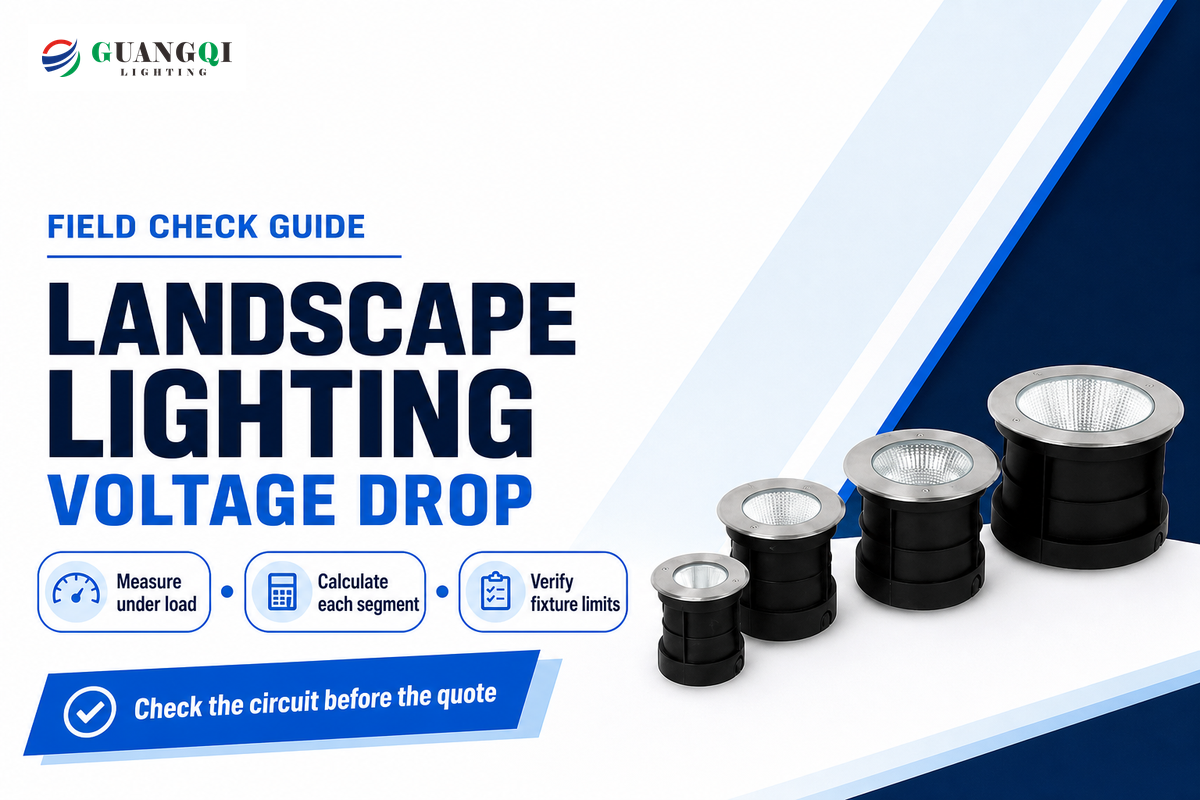
Landscape lighting voltage drop refers to the loss of voltage along a loaded cable and its connections. A transformer may have spare capacity while the last path light on a lighting circuit receives too little voltage. Before approving a replacement, check the power source, the route and the fixture specification. Match the measured supply to the commercial landscape lighting fixtures.
Landscape lighting voltage drop depends on circuit resistance and current. Calculate each cable segment using its downstream load, then compare loaded fixture readings with the exact product input range. A larger transformer alone cannot clear a cable or connection fault.
Quick checks before a repair
- Measure with the intended lights operating.
- Count both conductors when converting one-way distance into resistance.
- Check near and far light fixtures after any tap change.
- Keep AC transformer calculations separate from DC driver calculations.
Why voltage drop dims a landscape lighting system
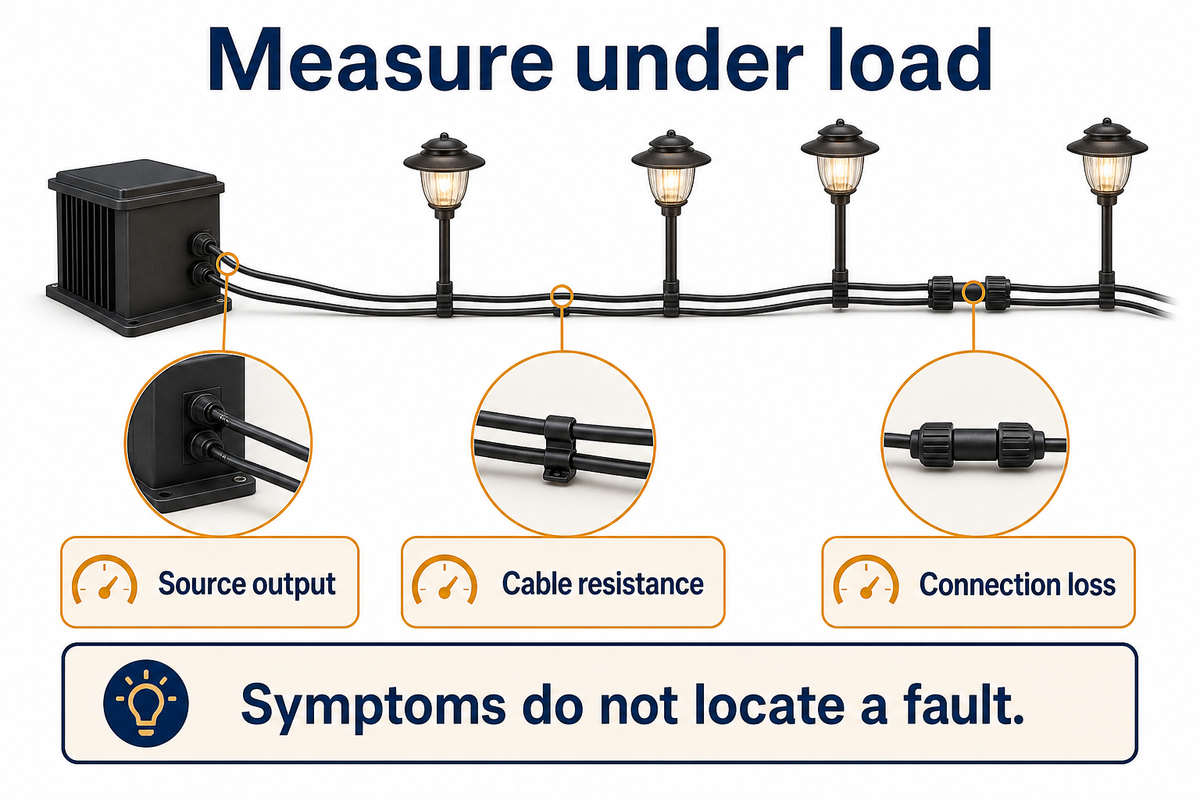
A low voltage landscape lighting system loses voltage where current passes through resistance. Long cable runs and an undersized conductor, and a damaged connector, can all contribute. Compare loaded source voltage with fixture voltage before assigning a cause; darkness, flicker and uneven brightness can also have optical or control-related explanations.
Penn State’s conductor-loss explanation discusses loss due to current and circuit resistance. Its recommendations in terms of the solar system are for that particular case. For outdoor landscape work the important physical relationship remains the same, but the limits of acceptance are taken from the lighting equipment selected.
| Observed pattern | Possible category | Next check | Limitations / Not suitable for |
|---|---|---|---|
| Whole circuit dark | Supply or control interruption | Confirm secondary output and timer state | No proof of cable loss |
| All lamps dim under load | Source sag or common feeder loss | Compare loaded source and first fixture | Spare transformer watts do not isolate cause |
| Far fixtures dimmer | Accumulated route loss | Record each junction and downstream load | Different optics can also change perceived brightness |
| Sudden change after one splice | Local connection or damaged conductor | Inspect that section with power isolated | Voltage readings alone do not identify the defect |
| One bulb dark | Lamp, socket or branch issue | Compare voltage with its specified range | Replacing bulbs blindly can miss a bad socket |
| Flicker when dimmed | Control or driver compatibility | Record dimmer setting and approved pairing | Steady voltage cannot exclude waveform problems |
| New problem after adding lights | Changed current or source loading | Update every affected segment | Old commissioning values no longer describe the circuit |
| Near light above allowed input | Tap or source selection | Check near and far fixture limits | A successful far-end reading does not clear the near end |
| Output looks weak at normal voltage | Optics, dirt or source aging | Check aiming and cleaning fixtures | Voltage cannot establish lumen output |
Consider a maintenance call after a floodlight was added beside architectural features. The owner sees dark spots at the far end and requests a larger unit. An installer first records the transformer’s loaded secondary output, then readings along the main cable. If output remains at 12.0 V while the far fixture reads 9.6 V, buying additional wattage hasn’t yet addressed the observed route loss. The next step is to compare sections and connections under the same conditions. If the source itself falls when the new lamp is operated, supply loading becomes part of the investigation. Neither pattern, by itself, identifies the failed part.
For a 12 V circuit, a measured 2.4 V source-to-fixture difference describes a loss under one recorded load. The reading doesn’t specify if the resistance is evenly distributed along the cable or concentrated at one of the terminations. Ask for sectional measurements before accepting a full replacement quote.
What is the acceptable voltage drop for lighting?
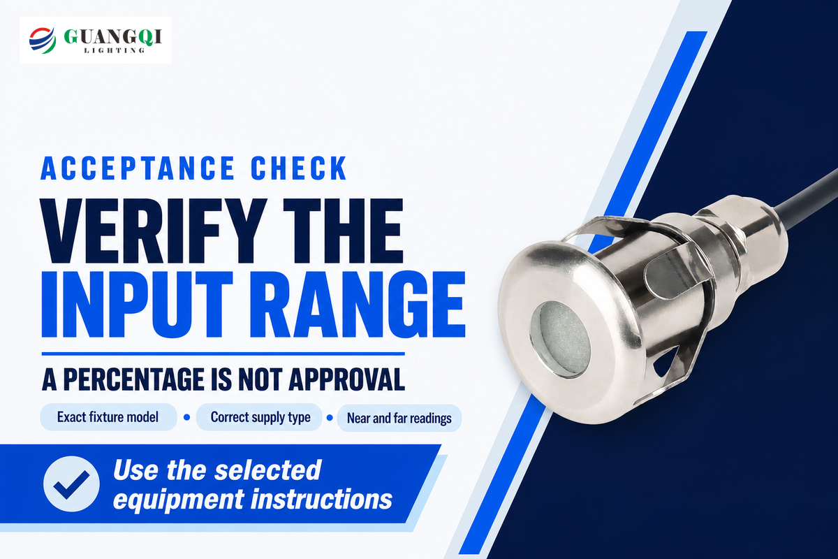
Acceptable landscape lighting voltage depends on the exact lamp or integrated fixture, its supply type and the project requirements. Design targets expressed in percentage terms can leave headroom; however, approval requires loaded readings to be evaluated within the manufacturer’s permissible input range. The nearest fixture must be examined just as closely as the most distant one.
FX Luminaire’s LX guidance specifies 10–15 V AC for its LED fixtures and a separate 10.5–11.5 V AC range for incandescent fixtures. These are attributed product-system examples. Don’t apply them to every LED, halogen lamp or 24V product. Lower voltage can still make consistent brightness with a regulated LED fixture within its defined operating range.
“do not in any way intend to conflict with, replace or supersede any national, state or local code.”
A common mistake is treating “under 5%” as proof of compliance. Five percent of 12 volts is 0.6 V; five percent of 24 V is 1.2 V. Those are arithmetic conversions, not universal installation limits. Define the design target and the product input limit separately.
A 12 V source with a 0.6 V loss leaves 11.4 V in a simple resistive estimate. Whether 11.4 V is acceptable depends on the documented fixture input and operating conditions. A supplier offering only a nominal voltage hasn’t supplied enough information to approve the run.
Calculate voltage drop segment by segment
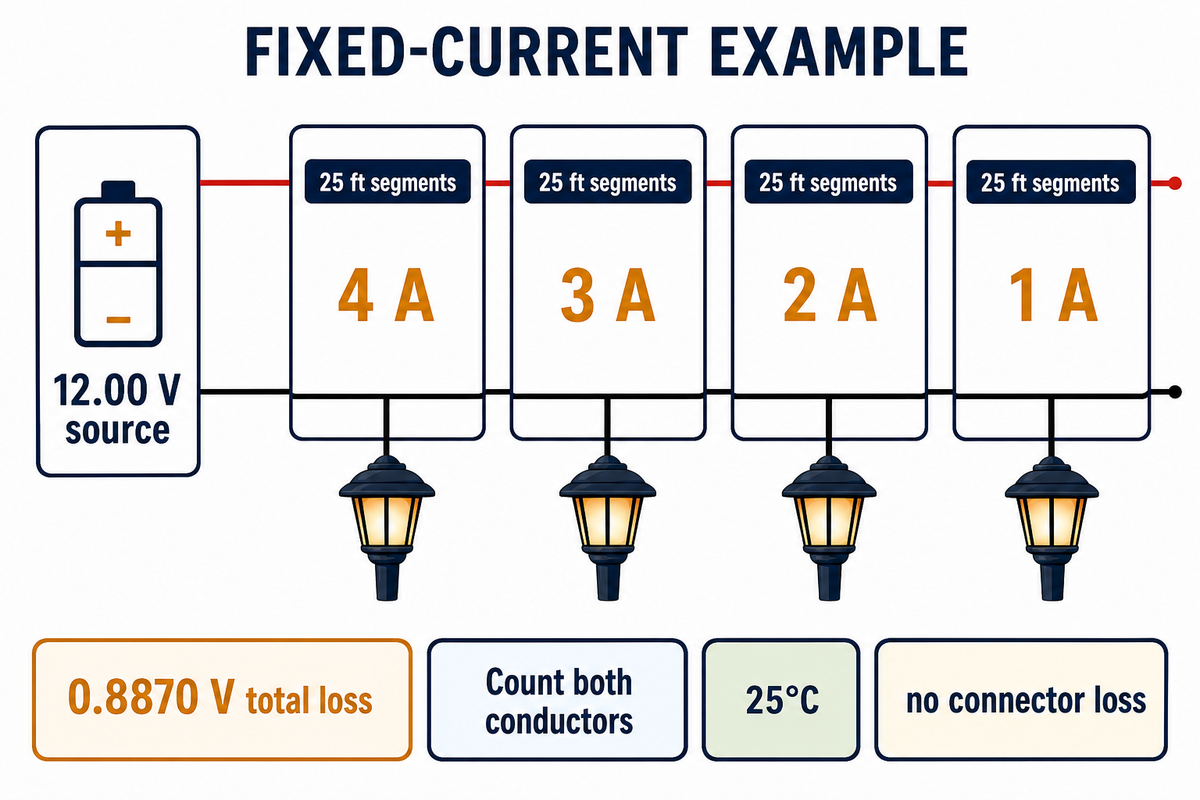
Estimate voltage loss of a segment of cable by calculating the total resistance of the pairs of conductors and considering the currents that flow through the remaining segments of the circuit downstream of that segment. Add the segment losses to estimate voltage at a fixture, then verify the installed circuit under load. Assuming fixed currents, and that cable loss is resistive, the calculation below shows that each segment of the circuit has a loss.
Applied Electrical Engineering Fundamentals details Ohm’s law and the relationship between resistance, the length of the conductor, and the area of the conductor. For a two-wire run, use VD = I × 2L × r, where I is segment current in amperes, L is one-way segment length in feet, and r is resistance in ohms per foot.
How much voltage drop is there in 100 feet?
There’s no single voltage-drop value for a 100-foot distance. Using Southwire’s published 12 AWG resistance at 25°C, four evenly spaced loads with assumed currents of 1 A each produce a 0.887 V total resistive loss. If we assume that the loads are concentrated at the end of the run and carry a total of four amperes, then the total loss will be 1.4192 V.
For this worked example, place one assumed 1 A load at 25, 50, 75 and 100 ft. Start with an assumed 12.00 V source. Each segment contains 50 ft of conductor after counting outgoing and return wires. Southwire SPEC 10115 lists 1.774 Ω/1,000 ft at 25°C for its 12 AWG stranded copper product. Each segment therefore has 1.774 × 50 ÷ 1,000 = 0.0887 Ω resistance. The first segment carries 4 A; the next carries 3 A after the first load branches off. Continue the same calculation for the remaining sections.
| One-way segment | Downstream current | Segment loss | Cumulative loss | Estimated fixture voltage |
|---|---|---|---|---|
| 0–25 ft | 4 A | 0.3548 V | 0.3548 V | 11.6452 V |
| 25–50 ft | 3 A | 0.2661 V | 0.6209 V | 11.3791 V |
| 50–75 ft | 2 A | 0.1774 V | 0.7983 V | 11.2017 V |
| 75–100 ft | 1 A | 0.0887 V | 0.8870 V | 11.1130 V |
In actual LED drivers, input current can vary; factors including the load, temperature, connections and AC waveform can affect the voltage-drop result. A contractor should not sell the calculated 11.113 V as a guaranteed site reading or substitute lamp watts for measured AC current without checking the load data.
Choose landscape lighting wire by resistance and load
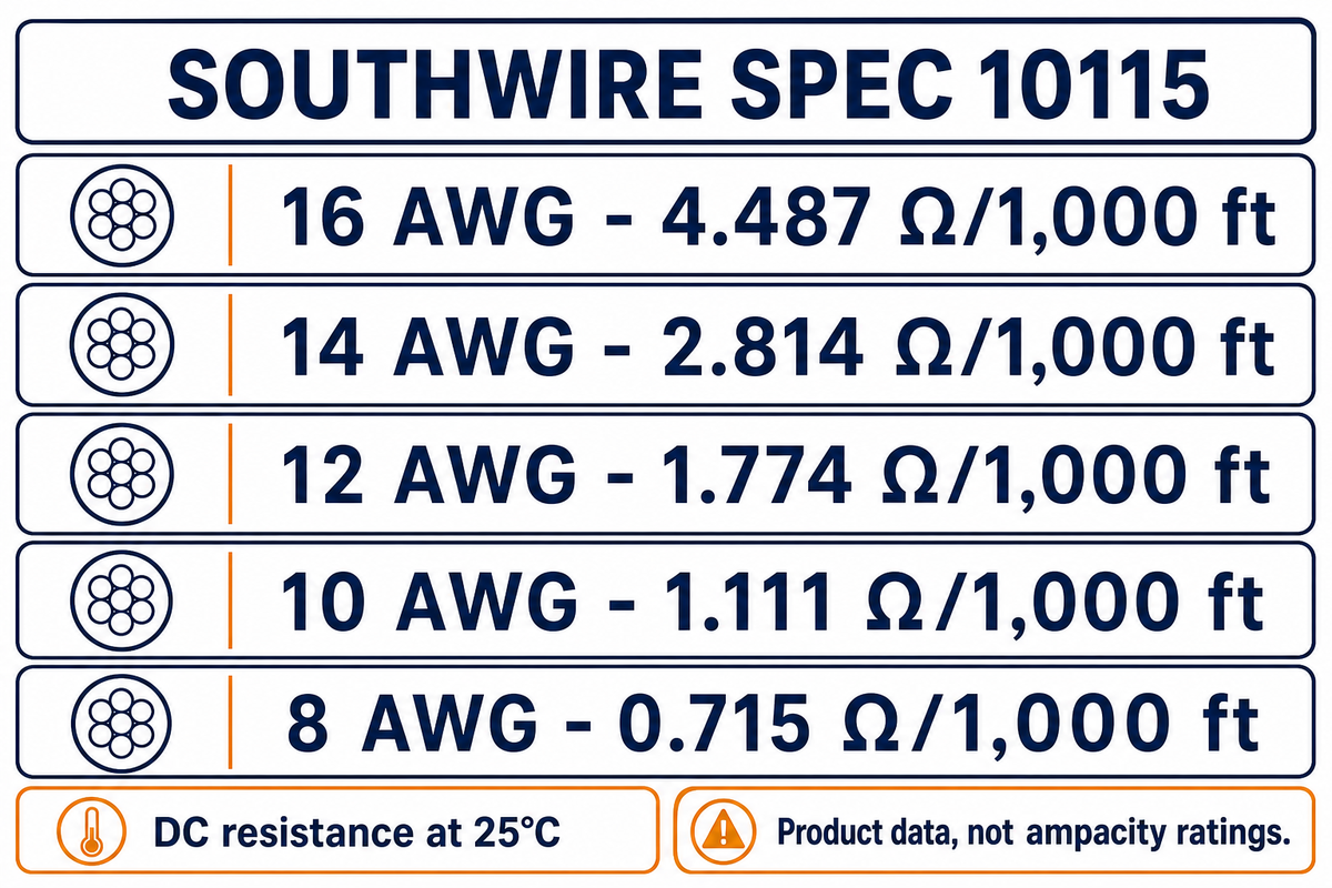
Choose landscape lighting wire according to required current, route length and permissible loss, and installation conditions. A lower American Wire Gauge (AWG) number indicates a larger conductor, but other factors such as temperature still matter. Use the resistance of the cable of interest, and check its installation and current carrying capacity.
| Wire size | Resistance | Boundary |
|---|---|---|
| 16 AWG | 4.487 Ω/1,000 ft | Recalculate for actual cable and temperature |
| 14 AWG | 2.814 Ω/1,000 ft | No fixed maximum run length implied |
| 12 AWG | 1.774 Ω/1,000 ft | Used only in the stated example |
| 10 AWG | 1.111 Ω/1,000 ft | Check terminal compatibility |
| 8 AWG | 0.715 Ω/1,000 ft | Check routing and connection requirements |
When installing low-voltage landscape lighting, requesting “12 gauge wire” without specifying copper construction leaves a buying gap. Don’t use a copper resistance table to substitute copper clad aluminum. Specify cable intended for outdoor use, suitable connections, and the recommended depth required by the applicable instructions and local codes.
For the assumed equivalent segment currents and lengths, 10 AWG cable of Southwire has a total loss of 0.5555 V, as compared to 0.8870 V loss for 12 AWG cable. The difference is 0.3315 V. The calculated improvement is 0.3315 V; trenching and termination work still determine whether replacement is a sensible purchase.
Compare thicker cable, separate branches and higher taps
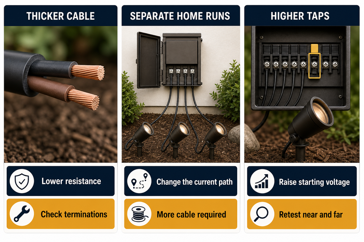
Thicker cables reduce resistance, separate home runs can change the current carried by a route, and higher transformer taps raise starting voltage. These remedies solve different constraints. Compare them against the same wiring layout and load, then confirm that every connected component remains within its permitted operating conditions.
How to fix voltage drop in LED lights?
First determine if the loss happens at the source, along the cable, or at a connection. Address verified defects before considering a larger conductor, a shorter route or separate branches. Use a higher tap only if the transformer provides it and both near and far fixtures remain within their approved input range.
Suppose a 60 ft feeder reaches two garden beds, each drawing an assumed 2 A. Splitting into branches at the beds still leaves 4 A in the common feeder. A proposal promising half the feeder loss merely because there are now two branches is incomplete. Separate home runs from the source can change that current path, but require more cable and compatible wiring terminations. Alternatively, a larger feeder reduces its resistance while leaving the branch layout intact. Have the installer identify and calculate the affected section of the common feeder. The quote should explain the change in length or current, rather than promise a percentage improvement.
Total Light’s calculation guidance explains distributed loads and end loads and provides a warning regarding excessive near fixture voltage. FX allows daisy-chaining of wiring for its LED system; Nate Mullen’s industry article advocates for an equalized hub. Neither is all-encompassing.
Moving a permitted circuit from a 12V tap to a 14V tap requires fresh measurements; a label doesn’t guarantee exactly 2 V more at every lamp. A 15V setting also needs a documented upper-input check. De-energize before changing connections, and never join different taps or transformer outputs.
Troubleshoot with a Loaded Voltage Handoff
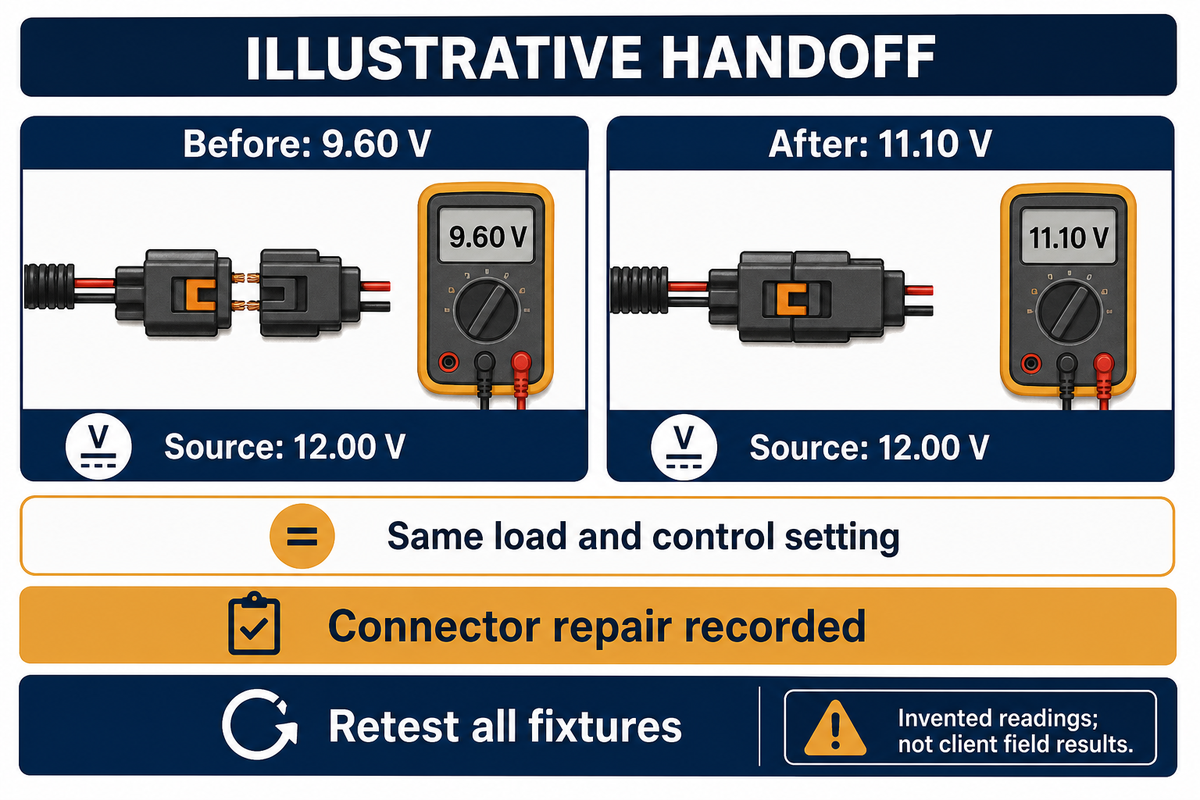
A Loaded Voltage Handoff is a measurement record for a repair quote. It captures the operating load, metering method and source, near and far fixture readings. Compare these observations with the exact product limits, and say what the next step will be, which could be a retest. The form organizes the evidence it contains; it doesn’t identify a failed component on its own.
Kichler’s troubleshooting instructions say to measure a drop-in fixture with the lamp in place. University of Southern California instrument guidance explains why true-RMS measurement helps with non-sinusoidal AC signals. Check the multimeter’s range and waveform limits, particularly with electronic supplies.
| Record field | Before investigation | After example repair | Limitations / Not suitable for |
|---|---|---|---|
| Supply / fixture basis | 12.0 V AC loaded; hypothetical fixture range 10–15 V AC | Same supply and fixture models | Range is an example assumption, not a Guangqi rating |
| Operating state | 4 fixtures on; dimmer at full output | Same state for comparison | Record different settings separately |
| Meter setup | AC volts; suitable true-RMS meter assumed | Same meter and range | Record model and waveform/frequency limits |
| Transformer terminals | 12.00 V | 12.00 V | A label marked 12V tap is not a measurement |
| First fixture | 11.65 V | 11.72 V | Check both minimum and maximum input |
| Last fixture | 9.60 V | 11.10 V | Before value fails the assumed 10 V minimum |
| Source-to-last difference | 2.40 V | 0.90 V | Steady-state difference alone cannot locate a fault |
| Cable / route record | 12 AWG copper; 100 ft one-way; four branch locations | Same route; connector repair recorded | Actual fixture currents and connector condition still needed |
| Approval / next check | Investigate local loss before approving cable replacement | Retest all fixtures and controls | Passing this example does not certify the installation |
In this illustrative maintenance decision, the source remains at 12.00 V while the last fixture improves from 9.60 to 11.10 V after a documented connector repair. The owner can compare the measurements because the fixture count and control setting stayed the same. The table supported a repair decision, but it doesn’t prove that all other unmeasured connections are working correctly. Before accepting the invoice, request readings at all fixtures and a check at the intended operating settings. Keep the photographs and the drawing of the route. It’s easier to investigate future callbacks, when the next installer can see what’s been changed.
Maintenance tips for repeatable measurements
Record the voltmeter model on the wiring drawing. Accessible secondary measurements belong to someone competent to perform them. Leave 120VAC or other line voltage testing to a qualified electrician. Power should be isolated for repairs or tap changes. A breaker that trips, heat damage, or exposed conductors should be investigated prior to further operation.
Keep AC transformers and DC drivers separate
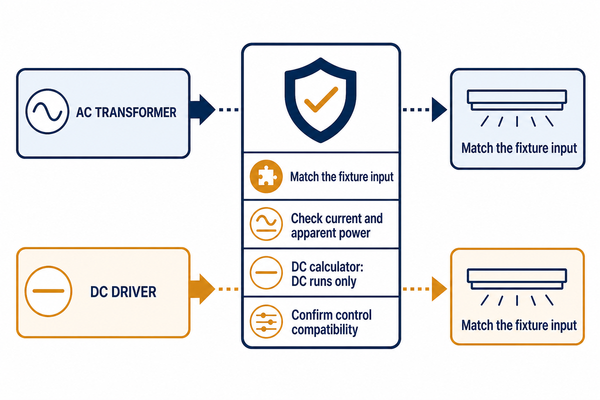
AC transformers and DC drivers require electrically compatible fixtures and different load assumptions. A 12VDC label doesn’t imply compatibility with a 12 V AC supply. For AC loads, use apparent power or current measurements, as appropriate; total wattage divided by voltage may understate current when power factor is less than 1.
According to the New Jersey Institute of Technology’s Power Laboratory Notes, apparent power is the product of RMS voltage and RMS current. A 12 VA load at 12 V will draw 1 A of current; the real power figure is dependent upon the load power factor. A rectifier in a lamp doesn’t mean that every bulb accepts both types of supply.
The U.S. Department of Energy’s Flicker Basics discusses driver and dimmer response as a cause of flicker. Normal, steady readings can’t rule this out. Record the control pairing and operating position before attributing instability of illumination to the wire.
Guangqi’s DC power-sizing and voltage-drop calculator addresses a DC run. Keep that in mind when using the calculator. A magnetic AC landscape circuit needs to be accompanied by its load information, and a 120V product must never be selected solely because it resembles a low-voltage lighting fixture.
Approve the supplier documents and repair scope

Approve a landscape lighting repair from an identified equipment schedule and measurable acceptance conditions. Request the lamp or integrated-fixture input range, supply instructions, cable details and commissioning record. General catalogs, certification logos, or transformer watt ratings can’t demonstrate that a specific combination will operate correctly on the proposed route.
The UL 1838 public catalog covers low-voltage landscape lighting systems and components. Its November 25, 2025 revision date doesn’t, by itself, disclose a new installation rule or certify a proposed product. Request the appropriate documentation for the exact item.
When not to buy a bigger transformer
Don’t choose a transformer merely because the far lamps look weak. Ask whether the existing source maintains its specified loaded output and whether the total connected load is within its instructions. A quote for a 200-watt transformer says little about a long run without current and cable data. The low voltage landscape lighting transformer selection guide covers the broader capacity decision; the route still needs a separate loss calculation.
Compare lighting options for electrical compatibility before changing models. Replacing halogen lamps with energy-efficient LEDs may change dimmer behavior and supply loading, even when nominal watts fall. Regular maintenance, including cleaning fixtures and confirming their aim, can address reduced apparent brightness without electrical replacement. Ask the supplier to distinguish the expected energy savings from corrected lumen output. These are different outcomes, and neither automatically follows from a higher transformer rating.
For a new outdoor space, match the landscape spot light specifications to the route prior to ordering. The landscape and garden lighting range supports product-family selection; send the fixture schedule and cable drawing to Guangqi’s lighting design services to discuss the required model documents.
Frequently asked questions
What causes voltage drop in landscape lighting?
View answer
Landscape lighting loses voltage as current passes through cable and connection resistance. Longer routes, smaller conductors and higher load can increase the loss. Loose or damaged connections can add a local problem. Measure the source and fixtures under the same operating load before deciding whether the route, supply or an individual fixture needs attention.
Is low voltage landscape lighting DC?
View answer
Low voltage landscape lighting can use AC or DC. Read the exact fixture and power-source labels rather than assuming all 12 V equipment is interchangeable. Some lamps accept both, but others don’t. A DC driver calculator does not automatically describe a magnetic AC transformer circuit or its LED load behavior.
Do I need a bigger transformer?
View answer
A larger transformer is justified when the required connected load and manufacturer instructions exceed the existing supply’s capability. It does not automatically remove resistance from a cable. If loaded source voltage remains appropriate but fixture voltage is low, investigate the route and connections before purchasing an unnecessary higher watt rating.
When should I worry about voltage drop?
View answer
Worry when measured input falls outside the product limits, performance changes, or components show damage. A sudden loss after landscaping work needs investigation even on a short run. Use the product limits and recorded load to assess whether each fixture receives proper voltage.
Can low voltage landscape lighting cause a fire?
View answer
Yes. Low voltage doesn’t remove the possibility of heating, damaged connections or an overloaded circuit. Stop using equipment with burning smells, heat damage, exposed conductors or repeated protection trips until a qualified person investigates. Follow manufacturer instructions for outdoor use, wiring and protection. DIY installation doesn’t justify working on exposed mains equipment; use professional installation where competence or local requirements demand it. A lower supply voltage also doesn’t excuse undersized conductors or unsuitable connectors. Before operation resumes, the repair record should identify the damaged section, the replacement components and the checks performed under the intended load.
Does landscape lighting voltage drop with temperature?
View answer
Copper resistance changes with temperature, so a calculation based on a published 25°C value won’t describe every site condition exactly. Use the cable manufacturer’s applicable data and confirm loaded voltage after installation.
Can you dim low voltage landscape lighting?
View answer
Only if the complete lamp, driver or transformer, and dimmer combination supports dimming. The Department of Energy describes driver response to dimmer output as a potential flicker cause. Test the approved combination at the intended settings. Set timers separately from dimming controls, and keep the measured operating state in the commissioning record so future maintenance can reproduce it. A lamp that behaves correctly at full output may need another check at a reduced setting. Changing the lamp model should also trigger a review of the approved control combination.
About the examples
The calculations and handoff readings are illustrative. Source-specific specifications were checked in October 2026. No Guangqi field-test dataset or product certification is claimed. Use the selected equipment instructions and local requirements for the actual installation.
References & Sources
- Conductor voltage-drop explanation, Pennsylvania State University, AE868.
- Guidelines for Low Voltage Landscape Lighting introduction, Association of Outdoor Lighting Professionals.
- Ohm’s law and resistance, David J. McLaughlin, Applied Electrical Engineering Fundamentals, University of Massachusetts.
- Landscape Lighting: Voltage Drop and Wiring Methods, OPE+, contribution by Nate Mullen and Unique Lighting Systems, 2015.
- Recommended Tools: Multimeter, University of Southern California, EE459Lx.
- Experiment 2: Power Factor Correction, New Jersey Institute of Technology; theory adapted from the source identified on that page.
- Flicker Basics, U.S. Department of Energy.
- UL 1838 public catalog, UL Standards & Engagement.