Get in Touch with GUANGQI



Updated August 2026
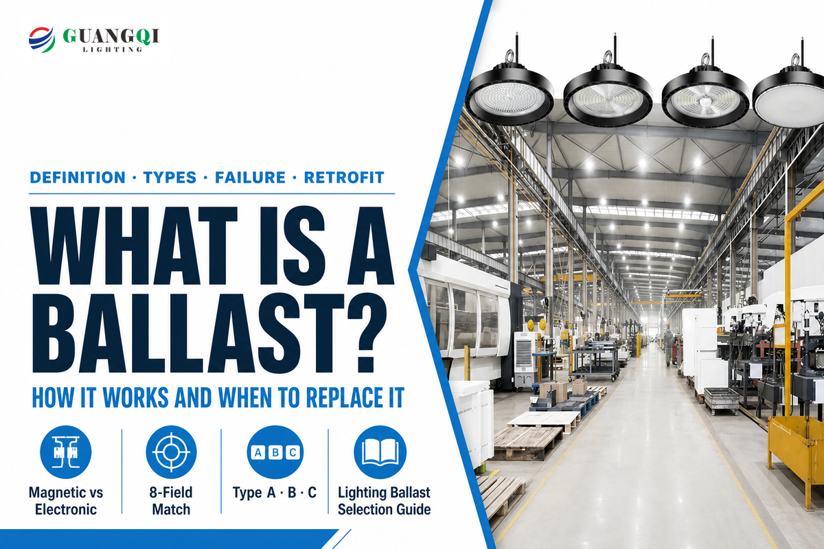
What is a ballast refers to an electrical ballast for lighting. It creates the conditions that a fluorescent or other gas-discharge lamp needs to start, then limits lamp current after the arc forms. It is not the weight used in ships, railways, or construction. This guide covers fluorescent and HID systems.
“Type A TLEDs are a direct replacement for fluorescent tubes and operate on the existing ballast(s).”
Choosing a ballast affects more than whether a lamp turns on. It determines the starting method, lamp current, fixture wiring, control compatibility, maintenance dependency, and sometimes the waste route when old equipment is removed. So the useful question is not simply “Does this replacement fit?” It is “Does this exact lamp, ballast, supply, wiring, and listed retrofit path form one approved system?”
1. What Is a Lighting Ballast?
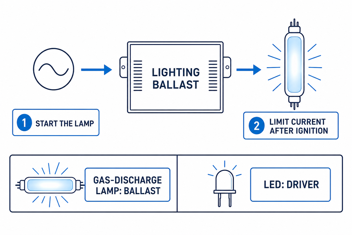
Lighting ballasts are current-limiting devices for a gas-discharge lamp. Under U.S. Department of Energy rules, the definition for a fluorescent lamp ballast covers two jobs: supplying the voltage and current needed to start the lamp, and limiting current during normal operation. Both jobs matter because the electrical behavior changes after ignition.
Inside a fluorescent or high-intensity-discharge lamp, current passes through an ionized gas rather than a resistive filament. Once the arc has formed, more current can reduce the arc’s effective resistance and invite still more current. This circuit therefore needs an external element that prevents runaway current flow. Ballasts provide that control while matching the source voltage to the lamp’s starting needs.
By function, a ballast is not automatically a transformer. Magnetic ballasts may use inductive windings, but their system role is current control. It is also not an LED driver. LED drivers convert and regulate power for semiconductor light-emitting diodes; a fluorescent ballast or HID ballast is designed around a gas-discharge arc. Regulatory meaning is source- and product-specific, yet the broader lighting concept includes fluorescent and metal-halide discharge systems.
The type of ballast in a lighting system follows the lamp rather than the familiar shape of a bulb or tube. Gas-discharge light fixtures may need a controlled high voltage for ignition and lower controlled lamp current afterward. Energy efficiency is a system result: an energy-efficient source still needs compatible control gear, optics, wiring, and controls.
Many discharge lamps require a ballast because the circuit cannot safely operate without a ballast or equivalent current-control gear. In magnetic equipment, a copper coil adds inductive impedance to limit the current on an alternating current supply. Electronic designs regulate the current through switched power supplies. Input current and power factor are separate nameplate fields.
Put simply, a ballast is a device that manages the amount of current through the arc. The ballast is to control that current after supplying enough voltage to start the source. Which circuit a ballast uses depends on the discharge technology; the right ballast must match both current and voltage rather than one nominal wattage.
Electrical Ballast and Light Ballast Terms
| Electrical term | Role in this article |
|---|---|
| Electrical ballast | Control gear for a gas-discharge lamp |
| Inductor or choke (electronics) | Magnetic impedance used for current control |
| Electrical network | Supply, control gear, wiring, source, and switching together |
| Power supply | Input stage that delivers electric power to the circuit |
| Ignition system | Starting arrangement for the specified discharge source |
| Electrode | Lamp element involved in the starting sequence |
| LED circuit and diode | Semiconductor path controlled by an LED driver |
| Resistor and electrical load | Circuit concepts that are not substitutes for a matched ballast |
| Alternating current or direct current | Input or internal current form stated by the approved equipment design |
Data point: Current U.S. fluorescent-ballast standards reviewed by the Department of Energy cover specified equipment from 120 V to 277 V at 60 Hz. Those numbers describe that regulatory scope, not a universal rating for every ballast worldwide.
2. How Does a Fluorescent Ballast Work?
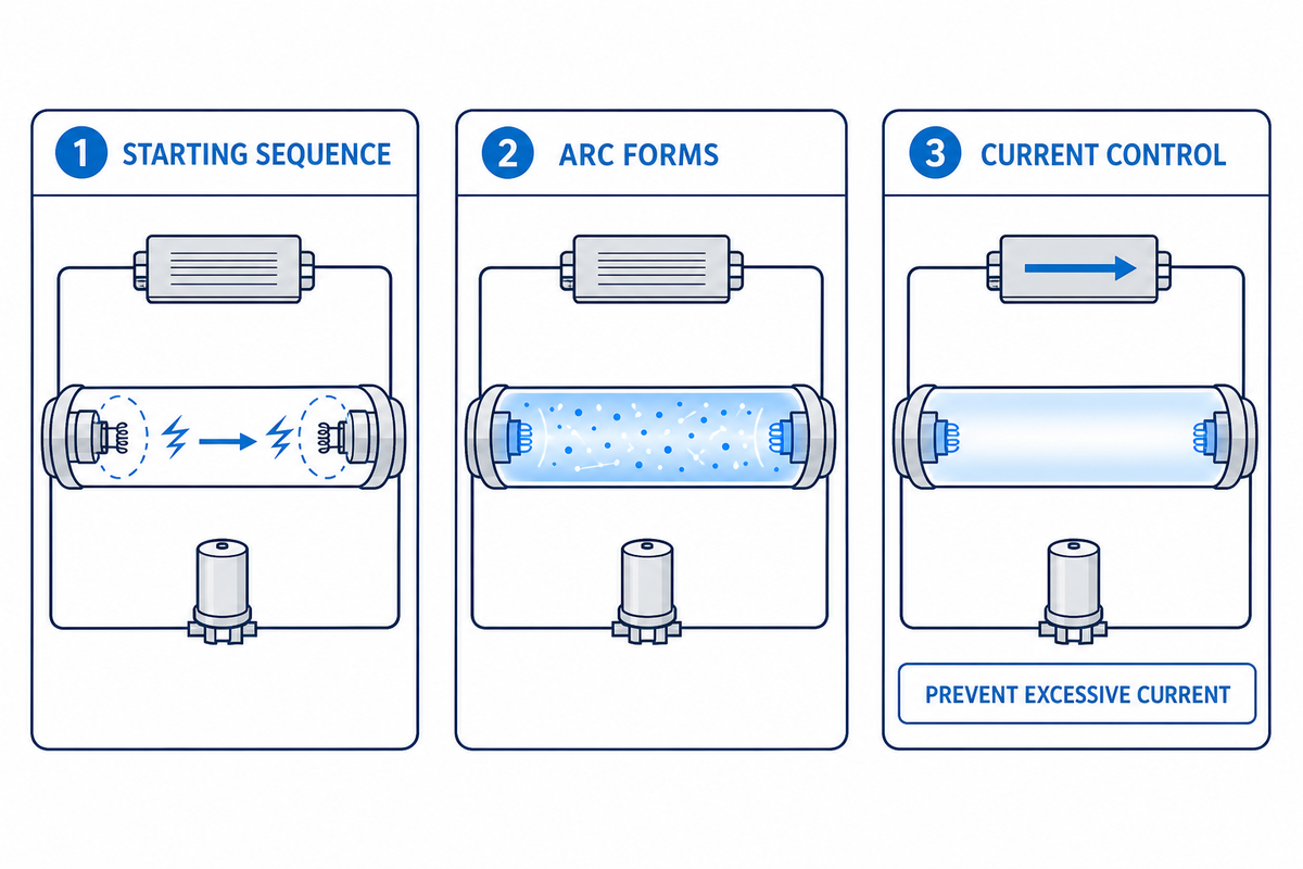
In a fluorescent system, the ballast prepares the lamp for ignition, allows an arc to form through the tube, and controls lamp current after ignition. Its detailed sequence changes with the start method. That is why two ballasts with the same nominal wattage can behave differently and cannot be treated as interchangeable parts.
Fluorescent Lamp: How the Ballast Works
At switch-on, the ballast applies a starting sequence suited to the lamp and circuit. Some systems heat the electrodes before applying the strike condition; others strike with little or no preheating. Once the gas ionizes, current crosses the lamp and produces ultraviolet energy. Phosphor coating converts that energy into visible light, while the ballast keeps the electrical current within the intended range.
With magnetic design, the ballast uses inductive reactance at the supply frequency to limit current. An electronic ballast first rectifies and conditions incoming power, then controls the lamp with electronic switching. High-frequency operation can reduce visible flicker and magnetic hum, but there is no single operating frequency that describes every electronic ballast. Model labels and manufacturer wiring diagrams remain controlling evidence.
The use of electronic ballasts changes the circuit architecture, not the matching obligation. Electronic ballasts can operate with rapid, programmed, dimmable, or instant-start designs when the model permits it. In all ballast systems, enough current must flow for the source to strike while control gear prevents excessive current afterward.
Starting behavior also affects lamp electrodes. Frequent switching, occupancy sensors, cold spaces, and long burn cycles do not create the same duty. Programmed-start ballasts can preheat electrodes before ignition, while an instant-start unit favors a faster strike. The correct choice follows the lamp system and switching pattern, not a blanket claim that one technology is always superior.
A rapid start ballast, programmed-start unit, or instant-start unit must match its approved lamps and lampholder circuit. A T8 tube label does not identify the complete system. The same rule applies to compact fluorescent lamps with separate control gear and to any dimmable ballast connected to a specified control interface.
Ballasts for Fluorescent Systems That Cannot Run Without a Ballast
Start-method reference: One Philips Advance technical guide lists less than 0.1 seconds for instant start, 0.5 seconds to 1.0 seconds for rapid start, and 1.0 seconds to 1.5 seconds for programmed start. These figures belong to the products and methods covered by that guide, not every ballast.
3. Magnetic vs Electronic Ballasts and the Start Methods That Matter
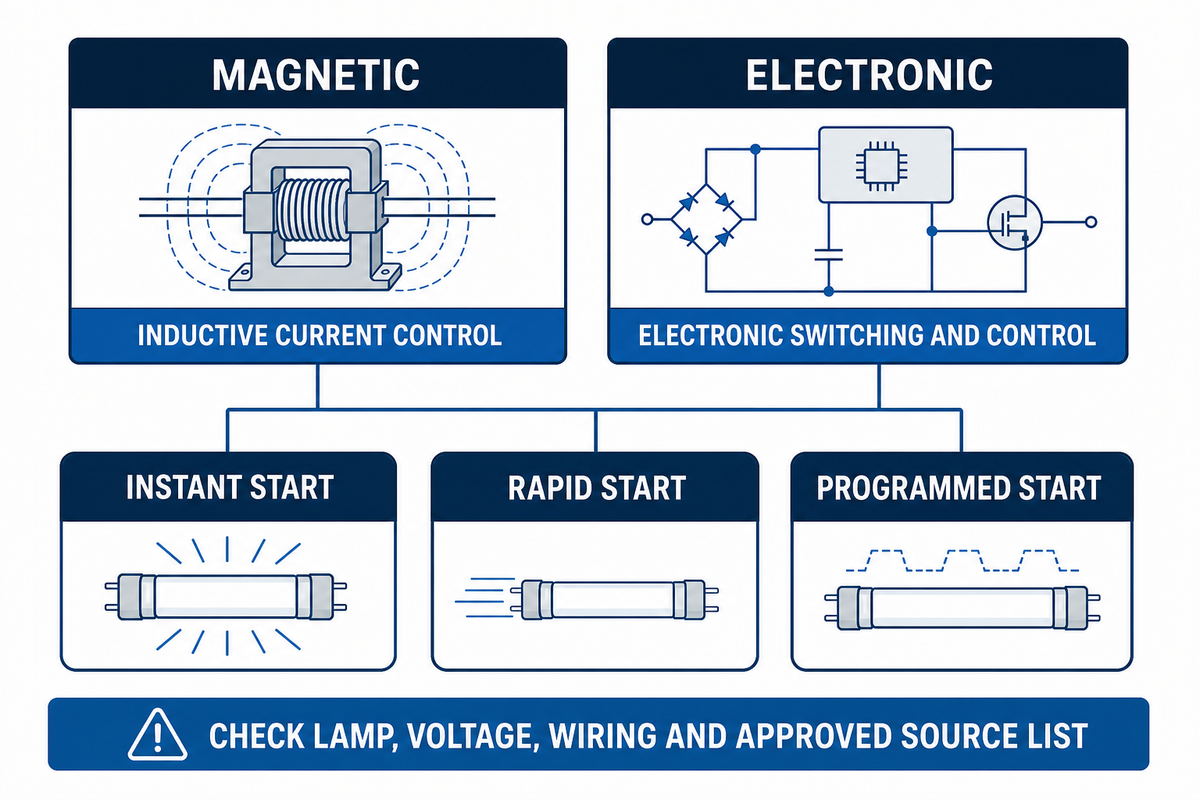
Magnetic and electronic ballasts use different circuit strategies, but their names alone do not establish compatibility. Any replacement must agree with the lamp family, lamp count, input voltage, starting method, ballast factor, wiring pattern, ambient limits, and control needs. Start with the nameplate, then check the full approved light source list.
Type of Ballast for Discharge Lamps
Different types of ballasts serve different discharge circuits. Ballasts for fluorescent sources do not become valid HID replacements because the housing looks similar. T8 fluorescent systems, compact fluorescent gear, and metal-halide equipment each retain their own approved circuit. Within the lighting industry, selection follows the marked source and wiring rather than appearance.
Ballasts in Lighting: Current Control for Fluorescent and HID Lights
Ballasts in lighting manage the flow of electricity so a discharge source can start and then remain within its intended current range. A control stage lets enough current flow for ignition; another part of the circuit reduces the voltage and regulates current after the arc forms. No universal claim that electronic units are more energy-efficient than magnetic ballasts applies without a defined light source-ballast system and test basis.
Magnetic ballast
Uses inductive components at line frequency. It may be heavier and may produce audible hum or visible light source modulation. Exact behavior follows the ballast and light source circuit.
Electronic ballast
Conditions incoming power and controls the light source electronically. It can support several start methods, dimming, and multi-voltage designs, subject to the listed model.
| control gear or method | Starting behavior | Selection concern |
|---|---|---|
| Magnetic fluorescent | Inductive current control | source circuit, starter arrangement, voltage |
| Electronic fluorescent | Electronic switching and control | source list, frequency effects, controls |
| Instant start | Fast strike with little or no electrode preheat | Switching frequency and lampholder wiring |
| Rapid start | Electrode heating during the start sequence | Grounding and circuit design |
| Programmed start | Controlled preheat before ignition | Frequent switching and sensor duty |
| Dimmable | Regulated output across a designed range | Control protocol, minimum level, source pairing |
| HID control gear | Starts and controls an HID discharge source | source chemistry, wattage, ignitor, voltage |
| Emergency fluorescent | Normal and emergency circuit coordination | Emergency equipment and commissioning path |
| Pulse-start metal-halide | Ignitor-assisted HID starting | Exact HID source, ignitor, capacitor, and supply match |
For HID service, the HID lamp, ballast, ignitor, and capacitor form one specified circuit. Fluorescent work uses the same compatibility principle: the ballast must control the current for the approved light source and starting method. A similar housing or connector does not prove an electrical match.
4. What Happens When a Ballast Goes Bad?
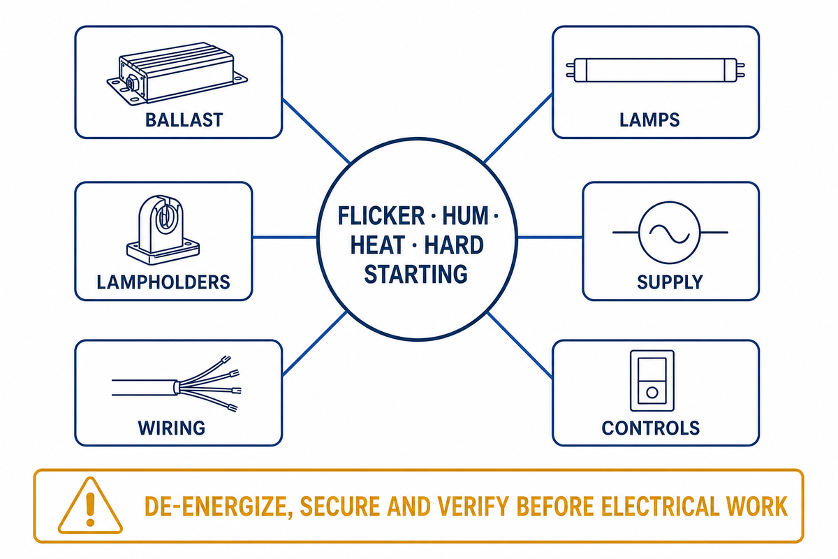
Ballast failure can cause delayed starting, cycling, dim output, flicker, hum, unusual heat, odor, or leaked potting compound. None of these symptoms proves that the ballast is the only failed part. Light sources, lampholders, supply voltage, wiring, temperature, controls, and grounding can produce overlapping signs.
Sound diagnosis checks the system in a safe order. Record the affected fixtures and light source behavior, compare light sources between known-good positions only where an approved procedure permits it, inspect for heat damage, and measure the supply and circuit with appropriate instruments. Manufacturer troubleshooting procedures should govern. Symptom-only diagnosis often turns one failure into an unnecessary order of incompatible replacement parts.
Electrical work belongs inside a controlled de-energization process. Using a wall switch is not proof that conductors are safe. Occupational Safety and Health Administration guidance of electrical lockout and tagging emphasizes disconnecting, securing, and verifying the circuit under the applicable procedure. Qualified electricians should own ballast testing, wiring changes, emergency-lighting connections, and final commissioning.
Old equipment creates a separate handling question. U.S. Environmental Protection Agency guidance states that fluorescent light ballasts manufactured through 1979 may contain polychlorinated biphenyls. Suspected units should not be opened or handled as routine scrap. Removed fluorescent light sources may contain mercury and can follow a different recycling or disposal route. Check current federal, state, and local requirements for each waste stream.
5. Check the 8 Disqualifiers Before a Ballast Match
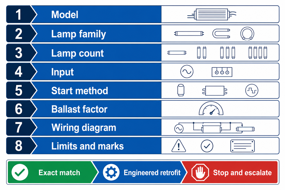
For purchasing, the ballast nameplate is the fastest route from a vague symptom to a defensible purchasing decision. Photograph the entire label and fixture wiring diagram before removal. Do not reduce the record to wattage. Eight fields form the minimum comparison worksheet for an exact replacement or an engineered retrofit.
- Preserve the exact manufacturer and model, including every suffix and revision.
- Capture the complete lamp family designation, not only tube length.
- Record the lamp count served by the ballast.
- Copy the full input: voltage, frequency, current, and any multi-voltage marking.
- Identify the start method: instant, rapid, programmed, pulse, or another stated method.
- Compare the ballast factor when the light source-ballast system publishes one.
- Preserve the wiring diagram, including lead colors, lampholder arrangement, and control connections.
- Record all limits and marks for temperature, enclosure, dimming, emergency, and certification.
This worksheet should produce one of three outputs. An exact match agrees with the approved light source and circuit data. An engineered retrofit changes the light source, ballast, driver, or wiring through a listed product path and project review. A stop and escalate result applies when a label is unreadable, wiring has changed, lampholders are degraded, emergency functions are unclear, or the proposed parts lack a confirmed compatibility path.
Ballast match check: one nominal wattage is only 1 of at least 8 purchasing fields. Supply rating, light source family, light source count, start method, ballast factor, wiring, and limits can all disqualify a look-alike replacement.
6. Do LED Lights Need a Ballast? Choose Type A, B, or C First
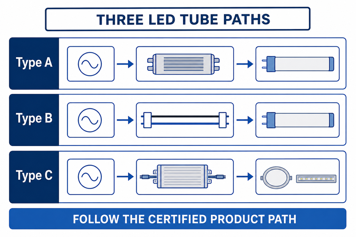
LED emitters need a driver, but an LED tube retrofit may retain, bypass, or replace the fluorescent ballast. The Type A, Type B, and Type C labels describe those system paths. They are not interchangeable wiring instructions, and a dual-mode product can qualify for more than one path.
LED Technology and Systems That Need a Ballast
- Type A: the LED tube operates through an existing ballast that appears on the product’s compatibility list.
- Type B: the ballast is disconnected and the LED tube receives line voltage through the prescribed lampholder wiring.
- Type C: the old ballast is removed or disconnected and a separate LED driver powers the light sources.
In LED lighting, an LED bulb or complete LED fixture has a driver architecture rather than a fluorescent ballast. A retrofit tube is different because it reuses part of an existing luminaire. Use the certified product path to decide whether the old ballast stays, the tube receives line voltage, or an external driver replaces the old gear.
When teams upgrade to LED lighting, LED technology can take several paths through an existing fluorescent luminaire. Type A LED light sources retain compatible control gear; other LED systems remove that dependency. The chosen route must preserve safe wiring, light levels, dimming capabilities, and stable light output. Reduced flicker or consistent light output must be verified by the selected product and commissioned system, not assumed from the word LED.
Some light sources carry dual Type A/B certification. UL Solutions explains that such a product can operate in either mode when its certification, markings, compatibility list, and instructions support the chosen arrangement. That exception is important: Type A and Type B are distinct system architectures, but they are not always mutually exclusive product identities.
Verify the retrofit in this order
- Identify: document the fixture, ballast, light sources, supply rating, controls, emergency function, and lampholders.
- Choose architecture: retain the compatible ballast, bypass it, use an external driver, or replace the luminaire.
- Verify: check certification, control gear compatibility, wiring, ratings, photometrics, controls, and local code.
- Commission: label altered luminaires, test controls and emergency behavior, and update the asset record.
The Department of Energy’s March 31, 2026 publication is a proposed determination, not a final new efficiency rule. Its market model projected fluorescent-ballast shipments falling 60% from 2020 to 2025, 85% by 2030, and 97% by 2035. Those are scenario projections for its analysis, not a facility-specific replacement forecast.
7. When Should You Replace the Ballast, Use an LED Driver, or Replace the Fixture?
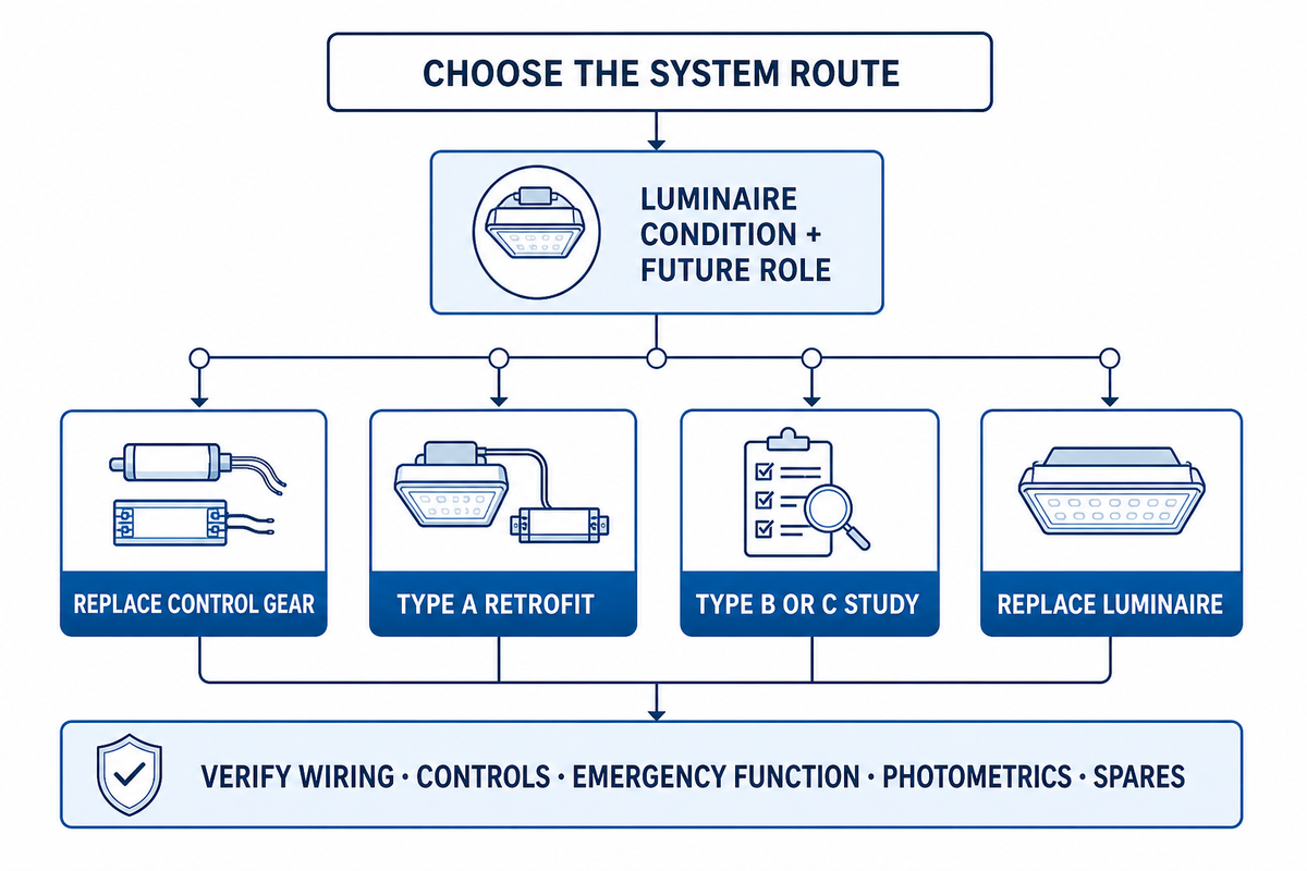
Selection follows the condition and future role of the whole luminaire. Control gear replacement may restore a serviceable fluorescent or HID luminaire with little physical change. Driver-based retrofit can remove a control gear dependency. Luminaire replacement can address damaged optics, wiring, controls, photometrics, and standardization together.
Efficient lighting is measured at the system level. The light produced, control response, emergency behavior, and maintenance path matter alongside input power. Existing fluorescent equipment may still have a defensible repair path, while another area may justify a new driver or luminaire after those factors are compared.
| luminaire type or condition | Likely route | Evidence needed |
|---|---|---|
| Sound luminaire; exact control gear available | Replace control gear | Exact source and wiring match |
| Compatible Type A tube approved | Retain control gear initially | Current compatibility list |
| control gear dependency is unacceptable | Type B or C study | Listing and wiring review |
| Existing controls must remain | Compatible driver or luminaire | Protocol and dimming tests |
| Emergency function present | Engineered system path | Emergency mode and duration test |
| Brittle or burned lampholders | Repair or replace luminaire | Socket and conductor inspection |
| Corroded housing or wiring | Replace luminaire | Environmental and enclosure rating |
| Poor optical condition | Compare new luminaire | Photometric target and layout |
| Mixed models across the site | Standardized retrofit | Inventory, spares, warranty |
| Unknown label or altered wiring | Stop and investigate | Qualified field verification |
Planning implication: retaining control gear can avoid immediate rewiring, but it preserves a two-part compatibility chain: the replacement tube must match the control gear, and the control gear must remain serviceable.
8. Who Owns Each Ballast Replacement Decision?
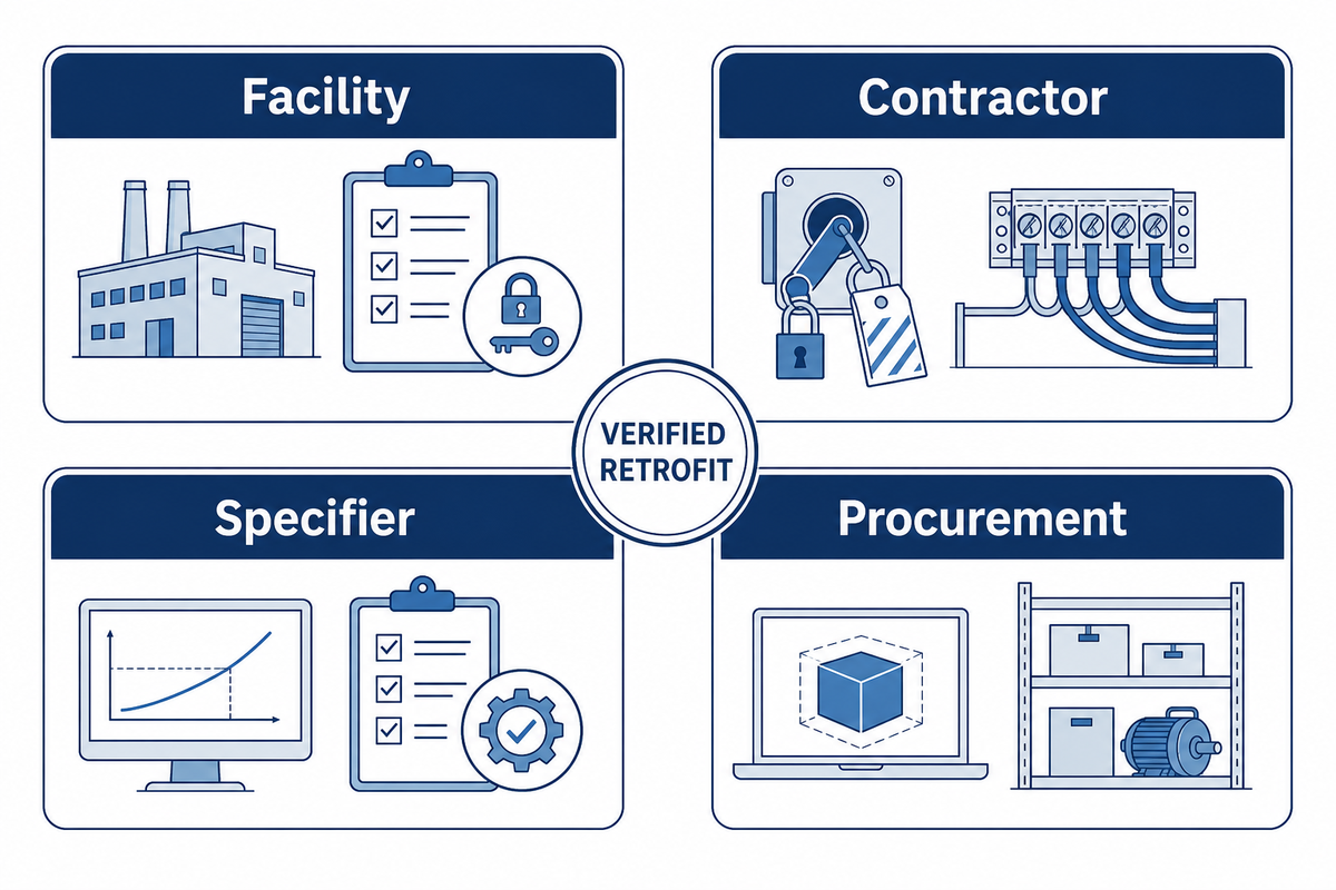
Reliable retrofit planning assigns each decision to the party that can verify it. Facility staff own the asset inventory and access constraints. Electrical contractors own safe isolation and field wiring. Specifiers own system performance. Procurement owns model control, commercial terms, spares, and traceable records.
Facility management should map luminaire quantities, locations, hours, switching patterns, access equipment, critical areas, and current failures. The contractor should verify supply rating, de-energization, conductors, lampholders, grounding, controls, and installed wiring. The specifier should check light levels, distribution, glare, color, dimming, emergency behavior, certification path, and commissioning criteria.
Procurement should normalize model numbers, approved equivalents, control gear or driver warranties, compatible spare light sources, lead times, and change control. Each unlabeled substitute should return to technical review. One small pilot area can confirm fit, light distribution, control response, and maintenance steps before a site-wide order, but it cannot replace the required listing or electrical review.
For broader upgrades, compare the existing asset record with the intended industrial lighting performance and the site’s lighting control system. Complex layouts may also need documented lighting design services. Where the architecture shifts to semiconductor sources, the LED driver and power-supply specification becomes part of the luminaire decision rather than a purchasing afterthought.
9. Common Ballast Replacement Mistakes
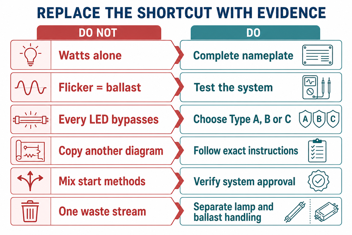
Most control gear replacement errors begin with an incomplete system record. Parts may look similar, the wattage appears close, or a retrofit tube is described simply as “ballast compatible.” Each shortcut removes a field that may control safety, starting behavior, light output, controls, or service life.
Do not
- Match by nominal watts alone.
- Treat flickering lights as proof of a bad control gear.
- Assume every LED tube bypasses the control gear.
- Copy a wiring diagram from another model.
- Mix start methods without system approval.
- Put old light sources and control gear in one waste stream.
Do
- Capture the complete nameplate and luminaire diagram.
- Test light sources, supply, sockets, wiring, and controls.
- Choose Type A, B, C, or luminaire replacement first.
- Follow the exact listed product instructions.
- Replace degraded lampholders and conductors.
- Separate ballast and mercury-lamp handling plans.
One final error is treating a product label as a complete project design. Product certification, control gear compatibility list, luminaire condition, local electrical requirements, photometric need, and commissioning result all have separate roles. If any one remains unknown, the technically honest output is to pause the order and close the evidence gap.
The practical takeaway
Control gear starts and controls a discharge light source, but the correct maintenance decision comes from the complete system. Record the label, light source, supply rating, start method, wiring, controls, luminaire condition, and retrofit architecture. Then choose an exact replacement, a listed LED path, a new luminaire, or a qualified stop-and-investigate decision.
Frequently Asked Questions
What is the purpose of a ballast?
View answer
Lighting control gear creates the electrical conditions that a fluorescent or other discharge light source needs to start, then limits current after the arc forms. That second job is essential because an operating discharge light source does not naturally limit its own current. The control gear must match the light source family, light source count, supply voltage, starting method, and wiring diagram; similar wattage alone does not prove compatibility.
What happens when a ballast goes bad?
View answer
Failing control gear may cause hard starting, cycling, low output, flicker, humming, unusual heat, odor, or leaked compound. Those signs are not a diagnosis. Worn light sources, loose lampholders, low supply voltage, damaged wiring, temperature, or controls can look similar. Qualified personnel should test the complete luminaire before a replacement is ordered.
Do LED lights need a ballast?
View answer
LED emitters need a driver rather than a fluorescent ballast. A retrofit tube may still operate through a listed compatible control gear as Type A, bypass it and receive line voltage as Type B, or use a separate external driver as Type C. Some products carry dual Type A/B certification. The product certification, compatibility list, luminaire wiring, supply rating, controls, emergency function, and lampholder condition must all agree with the selected path. Labels that say only “LED replacement” are not enough to authorize wiring work. Record who will label the altered luminaire and who will approve the final commissioning result before work begins.
How do I know if my light ballast needs replacing?
View answer
Check the light sources, lampholders, supply voltage, wiring, temperature, and controls before condemning the control gear. Compare the symptom with the exact control gear label and wiring diagram, then test the circuit under the manufacturer’s procedure. Replacement is justified when the control gear fails those checks, shows physical damage or overheating, or no longer has a safe and compatible light source path.
Can I replace a ballast myself?
View answer
Control gear replacement involves mains voltage and model-specific wiring. Qualified electricians should de-energize and verify the circuit, match the listed replacement, follow its exact diagram, and commission the luminaire. This article is a decision guide, not an installation procedure.
Is a ballast the same as an LED driver?
View answer
No. Fluorescent and HID control gear creates starting conditions and limits current through a gas-discharge arc. An LED driver converts and controls power for semiconductor light-emitting diodes. Retrofits can retain, bypass, or replace the old control gear, so the certified product path decides which device remains in the system.
References & Sources
- U.S. Department of Energy: Fluorescent Lamp Ballasts
- Federal Register: 2026 Proposed Determination for Fluorescent Lamp Ballasts
- UL Solutions: LED Luminaire Retrofit Kit Questions
- DesignLights Consortium: Product Eligibility and Use Designations
- Occupational Safety and Health Administration: Electrical Lockout and Tagging Interpretation
- U.S. Environmental Protection Agency: Disposal of Fluorescent Light Ballasts
- U.S. Environmental Protection Agency: Recycling Lamps That Contain Mercury
Planning a site-wide control gear replacement or LED conversion? Start with a luminaire inventory, the exact electrical architecture, and a defined commissioning plan. Guangqi Lighting can support project discussions for industrial luminaires, control integration, and matched driver requirements.