Get in Touch with GUANGQI



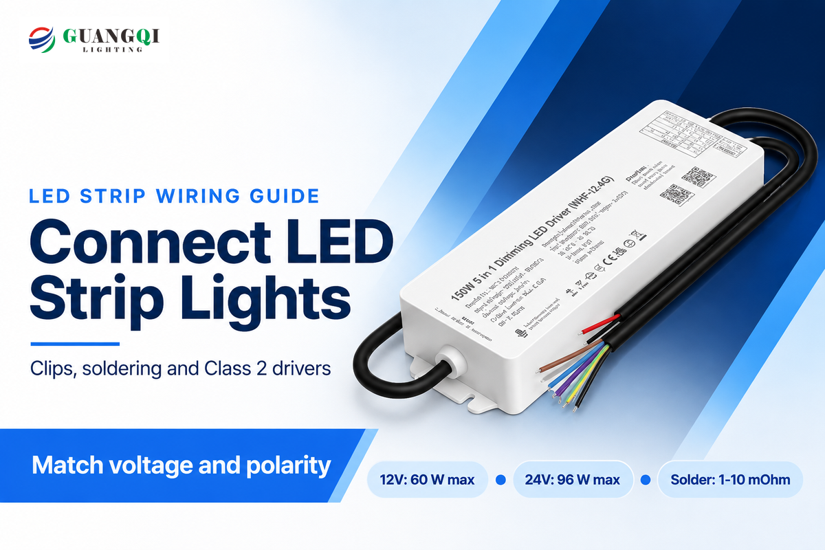
Match your strip voltage (12V or 24V DC) to a constant-voltage power supply and cut only across the printed copper pads. An LED strip light is a flexible circuit board, and anyone learning how to connect LED strip lights can join its sections safely.
Most post install callbacks start at mismatched junctions rather than dead diodes. Direct solder joints cut contact resistance to 1-10 mΩ, compared to 50-200 mΩ in push-pin clips. Longer runs also lose voltage along thin copper traces, requiring parallel feeders rather than daisy chaining.
How to Cut LED Strip Lights and Prep Copper Pads Before Connecting
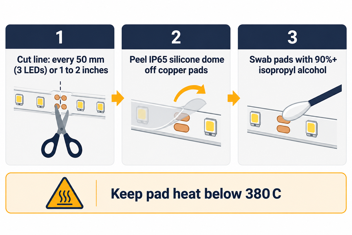
Cut flexible LED tape straight down along the printed scissor line bisecting the bare copper pads. According to Waveform Lighting, standard constant-voltage reels are shipped in 16-foot (5-meter) lengths with scissor cut lines spaced every 1 to 2 inches. First unplug the power supply, then clean the pads with isopropyl alcohol and clip them together.
Constant-voltage tape wires small emitter groups in series with a resistor and repeats those groups in parallel along the length of the tape. The U.S. Department of Energy’s LED Basics states that solid-state emitters need controlled forward current in every circuit branch. Cutting outside the copper mark opens that local series loop. Only that cut group goes dark, while the rest of the strip is still lit.
RH Strip Lighting’s engineering guide notes that LED strip copper pads are thin and delaminate when forced into a clip at an angle or heated above 380°C. Common strip widths include 5, 8, 10, 12, and 15 mm. SuntechLite’s 10 mm DC 12V 60 LED/m RGB tape places a cut mark every 3 LEDs (50 mm).
Can you cut LED strip lights?
Yes, you can cut LED strip lights safely along the factory scissor icon splitting each pair of copper pads. SuntechLite’s 60 LED/m DC 12V strip cuts every 50 mm (3 LEDs), and Waveform Lighting reports typical reel cut lines every 1 to 2 inches. Cutting off-mark disables only that single series group.
Waterproof and digital strips need one extra prep step after you cut LED tape. On IP65 splash-coated tape, use a craft knife to gently score the silicone dome just behind the cut line, and peel the clear layer off the copper pads. RH Strip Lighting specifies swabbing the pads with 90%+ isopropyl alcohol so residual silicone never blocks contact. On addressable strips, ensure data enters DIN rather than DOUT.
Connecting LED Strip Lights Without Soldering: Choosing the Right Clip Connector
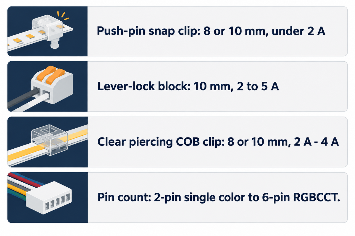
Choose a solderless connector by matching four specs: PCB width (usually 8, 10 or 12 mm), pin count (2 to 6), diode style and current. Keep current under 2 A on push-pin clips and 2 to 5 A on lever-lock blocks, and solder permanent runs. Align + to +.
SuntechLite’s dimensional guide lists flexible PCB widths from 3 mm to 20 mm, with 5, 8, 10, 12, and 15 mm most common. Placing an 8 mm strip inside a wider clip housing lets metal teeth miss the pads or short adjacent traces. High-density COB tape adds another trap. Its continuous phosphor bead removes visible LED dot spacing to form a smooth line of light, hiding pad edges from standard SMD clasps. Choose clear polycarbonate piercing strip connectors whose teeth bite through the underside copper.
Mechanical strain relief protects tool-free joints over time. In USPTO patent US8714772B1 (assigned to Inspired LED LLC), engineers showed that cable pull and vibration loosen conventional clasps on sub-1 mm tape. Their design adds an approximately 1.5 mm rigid planar support platform to anchor the strip. RH Strip Lighting targets under 20 mΩ joint resistance for any current above 3 A, a level only soldered joints (1-10 mΩ) consistently meet.
How do you connect LED strip lights after cutting?
Flip open a width-matched solderless clip, and slide the cleaned copper pads fully underneath the metal contact prongs. Align + to + across both strip ends and press the latch or spring-loaded lever shut, until it locks in a fully flat position. Gently tug on the joint and test the power before mounting.
Select drivers and accessories by their model-specific Class 2 safety markings, not by brand name, because many catalog series mix Class 2 and non-Class-2 units. Match exact PCB width, pin pitch, and ANSI/UL 2108 Edition 2 low-voltage markings on the individual datasheet. Check your strip specs against the 4-Dimension Connector Pairing Guide table below before ordering.
| Strip Family | Typical PCB Width | Pin Count | Connector Mechanism | Recommended Current Limit | Primary Field Failure Mode |
|---|---|---|---|---|---|
| Ultra-narrow accent SMD | 3 mm – 5 mm | 2-pin (+V, -V) | Direct wire solder (clips rare) | Up to 2 A | Pad lift if iron exceeds 380°C or 5 seconds |
| Standard single-color SMD (IP20) | 8 mm or 10 mm | 2-pin (+V, -V) | Push-pin gapless snap clip | Under 2 A (dry indoor) | Contact oxidation climbing to 150–300 mΩ within 12 months |
| Commercial high-output single-color | 10 mm | 2-pin (+V, -V) | Spring-clamp lever-lock block | 2 A – 5 A | Copper pad peel if inserted at an angle |
| High-density dotless COB | 8 mm or 10 mm | 2-pin (+V, -V) | Clear insulation-piercing COB clip | 2 A – 4 A | Dark shadow gap if opaque SMD clip is used |
| Tunable white (CCT) | 8 mm or 10 mm | 3-pin or 4-pin | 3/4-pin jumper connector or lever clip | 2 A – 4 A total | Warm/cool channels reversed at polarity mark |
| Analog RGB color-changing | 10 mm – 12 mm | 4-pin (+V, G, R, B) | 4-pin snap or wired corner jumper | Under 2 A (push-pin) or 2–5 A (lever) | Swapped R/G/B pins scrambling mixed colors |
| Analog RGBW (4-channel) | 10 mm – 12 mm | 5-pin (+V, R, G, B, W) | 5-pin lever clip or 20 AWG solder | 2 A – 5 A (solder above 3 A) | Common-anode +V pin overheating at full white |
| Analog RGBCCT (5-channel) | 12 mm – 15 mm | 6-pin (+V, R, G, B, WW, DW) | Pre-tinned wire solder preferred | Solder preferred above 2 A | Fine-pitch 6-pin misalignment causing shorts |
| Addressable pixel IC (single-wire / SPI) | 8/10/12 mm (up to 20 mm) | 3-pin (+V, DIN, GND) or 4-pin (+V, DIN, CLK, GND) | JST-SM lead or direct solder | Inject power separately >3 A | Feeding signal into DOUT or skipping CLK wire |
Soldering LED Strip Lights and Bridging 90-Degree Corners or Cabinet Gaps
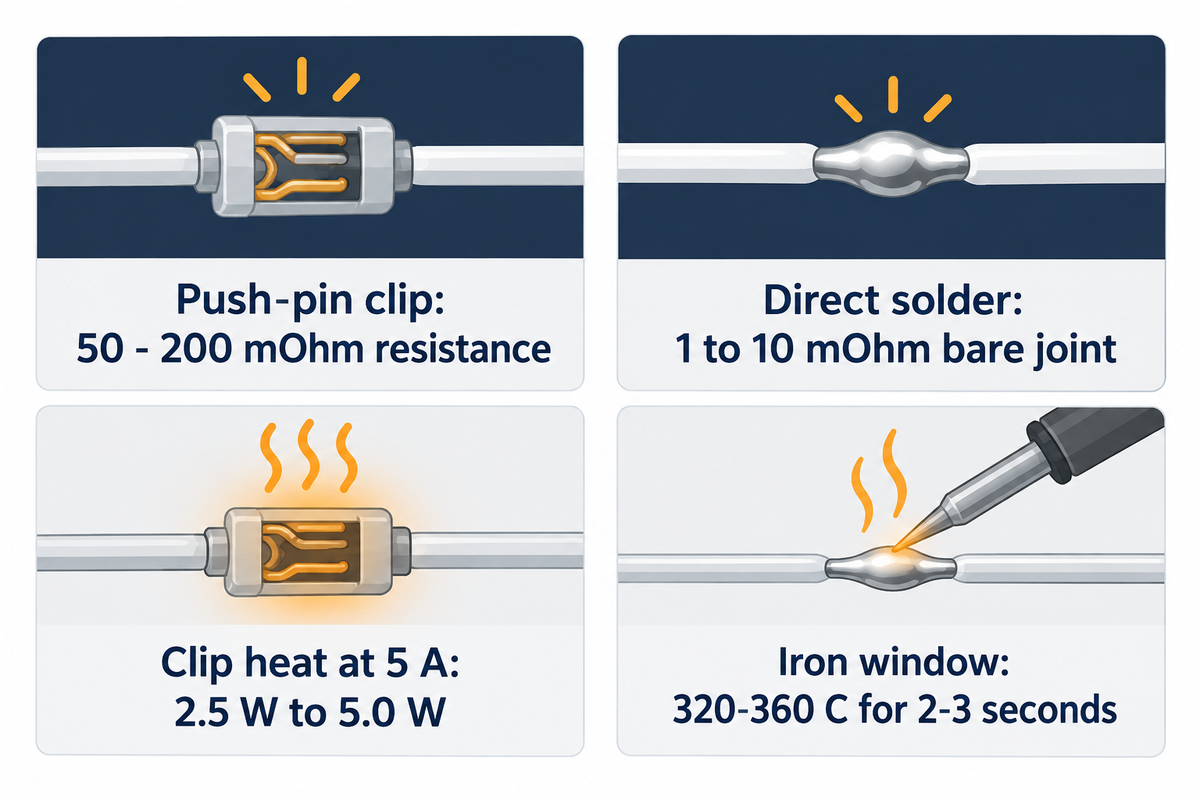
For LED strip joints that require permanent connections, soldering is more dependable than clip connectors. Choose solder over clips if load current is greater than 3 A per channel and a 2-5 A lever-lock block can’t achieve the sub-20 mΩ resistance. Slim aluminum channels, moist kitchens, outdoor runs, and vibrating panels also require soldering. Set a temperature-controlled iron to 320–360°C and cap heat dwell at 2–3 seconds per pad.
Soldered joints reduce contact heating seen on cheap plastic clips in cabinet lighting to only a fraction of a watt. RH Strip Lighting reports solder joint resistance of 1 to 10 mΩ, roughly 5 to 200 times lower than the resistance in a push-pin clip (50-200 mΩ). Because joint heat scales with P = I²R, lower-voltage strips carrying twice the current generate four times the heat across identical clip resistance.
Example: Compare two 60 W under-cabinet runs at standard strip voltages. Dividing watts by volts yields 60 ÷ 24 = 2.5 A at the higher voltage, and 60 ÷ 12 = 5.0 A at the lower voltage. Across a 100 mΩ clip at 5 A, RH Strip Lighting calculates 2.5 W of localized heat. After six months of humidity, oxidation increases that clip to 200 mΩ and 5.0 W of heat, browning the diffuser. Soldering keeps joint dissipation below 0.25 W at 5 A and slides cleanly into recessed channels. Insulate bare solder joints from metal channels on Class 2 luminaires covered by low-voltage lighting system standards.
Keep DIY soldering inside a tight thermal window so copper pads stay intact. Use 63/37 eutectic solder (183°C melt) or lead-free SAC305 (217°C melt) at 320–360°C, keeping LED junctions below 120°C. Tin the cleaned pad for 1 second, then strip and tin 3–4 mm of 200°C heat-resistant silicone wire. Fuse both conductive surfaces for 2–3 seconds and hold the wire motionless for 5 seconds. RH Strip Lighting notes pad delamination starts above 380°C or past 5 seconds of heat. Never fold tape flat at a 90-degree crease. Jump corners and range-hood gaps with flexible cable or an L-shaped jumper connector, comparing options in our Clip-vs-Solder Field Tradeoff Blueprint reference table below.
| Comparison Factor | Push-Pin Snap Clip | Lever-Lock Connector | Direct Solder + Heat Shrink |
|---|---|---|---|
| Initial contact resistance | 50 – 200 mΩ | 20 – 80 mΩ | 2 – 15 mΩ (1–10 mΩ bare joint) |
| 12-month humid oxidation drift | Climbs to 150 – 300 mΩ | Stable spring clamp force | Negligible metallurgical drift |
| Safe continuous current per channel | Under 2 A (never above 3 A) | 2 A – 5 A | Limited by wire gauge & PCB trace |
| Heat dissipated at 5 A load | 2.5 W (100 mΩ) to 5.0 W (200 mΩ) | 0.5 W – 2.0 W | 0.05 W – 0.38 W |
| Slim aluminum channel fit | Often jams slim extrusions sized tightly to strip | Requires wide/deep profile | Fits slim recessed profiles cleanly |
| 90-degree corner & cabinet gap routing | L-clip or wired clip jumper | Wire-to-strip lever bridge | Custom 200°C silicone wire loop |
| Vibration & vehicle suitability | Intermittent dropouts | Moderate indoor stability | Permanent mechanical bond |
| Outdoor splash & rain suitability | Not suitable outdoors | Dry indoor commercial only | Splash/rain seal with alkoxy silicone + shrink |
| Reusability after disconnect | Contact resistance rises with each reuse cycle | Tool-free lever release | Desolder required |
How to Connect LED Strip Lights to a Power Supply (Plug-In Adapter vs Screw-Terminal Driver)
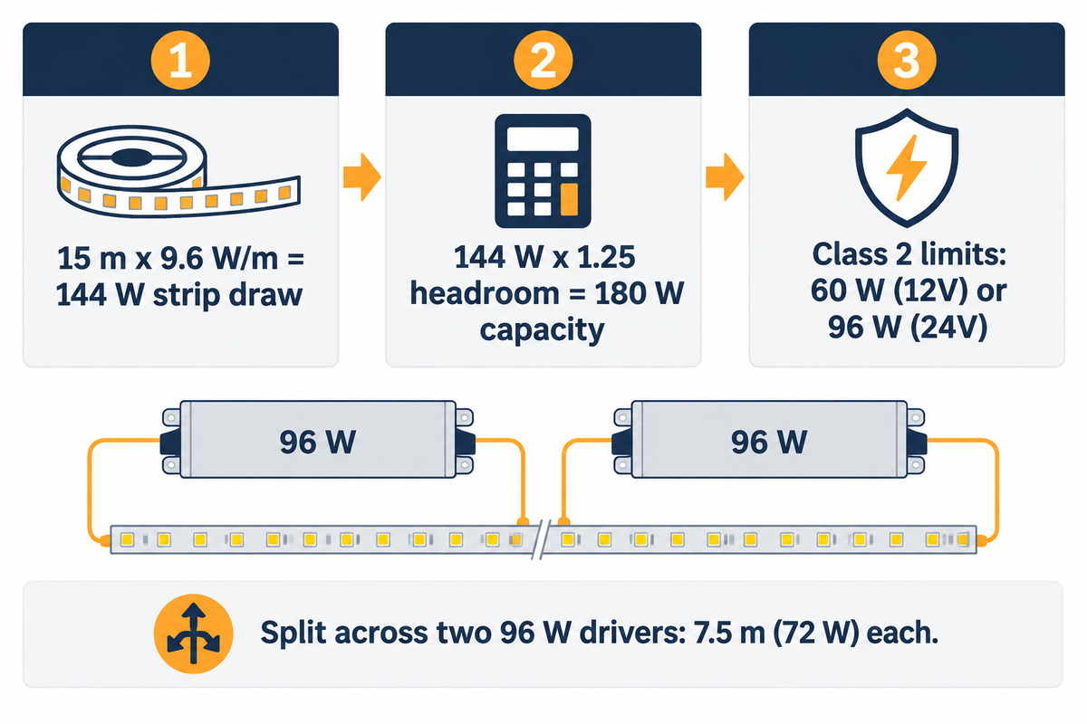
Match your driver’s DC output voltage identically to the strip label. Multiply strip watts per meter by total run length, then multiply by 1.25 for an 80% continuous load ceiling. Keep each NEC Class 2 circuit within 60 W on 12V systems or 96 W on 24V systems.
Wattage determines power supply capacity, not visible brightness. Waveform Lighting’s tutorial notes that emitter efficacy varies across strips. Rated lumens per foot (450 lm/ft or 1,500 lm/m minimum for task output) measures brightness, while watts govern driver sizing and energy efficiency. Under UL 2108 Edition 2 (revised September 27, 2024), low-voltage lighting power units cap output at 25 A under NFPA 70 Article 411. IAEI Magazine’s UL Question Corner confirms that NEC 725.121(A) also permits Listed Limited Power Source (LPS) supplies on Class 2 circuits.
How do I connect my LED strip light to my power supply?
For a desktop power brick, plug in the strip’s barrel connector (or clamp red (+) and black (-) leads into a screw-barrel adapter), and then plug into the wall outlet. For an enclosed driver, connect AC line, neutral and ground to their respective terminals, and connect +V and -V to the DC output screws.
Assumed inputs for multi-reel sizing: three 5-meter reels (15 m total) of energy efficient 24V tape rated at 9.6 W/m. That matches Myledy’s 10 m × 9.6 W/m = 96 W benchmark, and we add a 1.25× headroom factor. Total strip draw equals 15 m × 9.6 W/m = 144 W, requiring 144 W × 1.25 = 180 W of driver capacity. Because one 24V NEC Class 2 output caps at 96 W, divide the run across two independent 96 W Class 2 drivers. Each driver feeds 7.5 meters (7.5 × 9.6 = 72 W, or 72 ÷ 96 = 75% load). Power both ends of each 7.5-meter zone to stay inside the 7-meter single-end limit. Check your layout in our LED power sizing and voltage drop calculator and compare supplies from commercial Class 2 LED driver manufacturers.
Keep the two 96 W +V buses electrically isolated rather than tying constant-voltage outputs together. Tying two Class 2 outputs together also violates the single-circuit Class 2 power limit. Since the cost of Class 2 drivers and the connector kit varies based on wattage, enclosure rating, and dimming protocol (quote per model datasheet), connect the power only after verifying DC polarity.
Connecting Multiple LED Strips: Series Daisy-Chaining vs Parallel Wiring and Power Injection
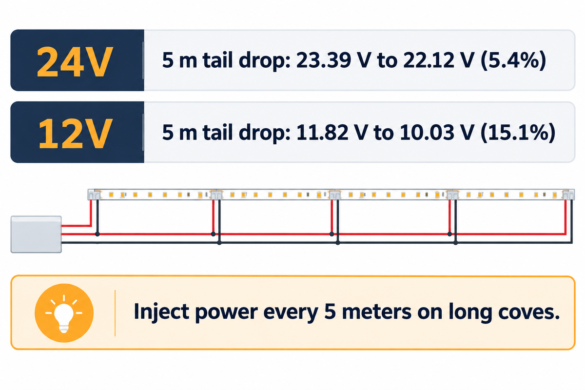
Wire multiple 5-meter LED light strip reels in parallel home-run branches back to your power supply, or inject power at the midpoint and tail. Avoid daisy-chaining reels end-to-end, because pushing the downstream reels’ current through the thin copper foil in Reel 1 (the first reel) will starve the diodes at the far end.
Myledy’s bench measurements on a single-end 5-meter 2835 120 LED/m (9.6 W/m) strip lighting run show how fast foil resistance adds up. Tail voltage fell from 23.39 V to 22.12 V (1.27 V, or 5.4% drop) at 24V DC. Equivalent 12V tape dropped from 11.82 V to 10.03 V (1.79 V, or 15.1% drop), which dimmed the tail LEDs and shifted the adjustable white mix toward yellow. Doubling supply voltage at equal wattage halves load current, and 2–3 oz copper PCBs reduce trace loss further.
How to connect LED strip lights in parallel?
Pull dedicated two-conductor feeder wires from each strip section straight back to the power supply’s +V and -V terminals. Alternatively, you can group all positive leads in one lever-nut block and all negatives in a second block; thus, each reel gets full source voltage independently.
When a continuous ceiling cove blocks home-run splits, run an insulated bypass feeder next to the channel and inject power every 5 meters. RH Strip Lighting mentions that end-injecting a 10-meter run cuts each segment’s feed path to 5 meters. Our walkthrough on low-voltage cable voltage drop calculations covers formulas to determine feeder resistance. Size your feeder wire using the Run-Length & Feeder-Gauge Drop Budget below, where the wire-gauge columns reflect Myledy’s <3% feeder-cable drop distances.
| System Voltage & Load | Load Current | Recommended Strip Feed (One-End / Dual-End) | 20 AWG Cable (<3% Feeder Drop) | 16 AWG Cable (<3% Feeder Drop) | 14 AWG Cable (<3% Feeder Drop) |
|---|---|---|---|---|---|
| 12V DC · 10 W strip branch | 0.83 A | Up to 5 m / 10 m | 5.5 m (18 ft) | 16.4 m (54 ft) | 26 m (86 ft) |
| 12V DC · 30 W strip branch | 2.5 A | Up to 5 m / 10 m | 1.8 m (6 ft) | 5.4 m (18 ft) | 8.8 m (29 ft) |
| 12V DC · 60 W Class 2 ceiling | 4.2 – 5.0 A | Split parallel ≤5 m | 0.9 m (3 ft) | 2.7 m (9 ft) | 4.2 m (14 ft) |
| 24V DC · 10 W accent run (≈2.1 m at 4.8 W/m) | 0.42 A | 4.8 W/m family rated up to 10 m / 20 m | 25.9 m (85 ft) | 65.5 m (215 ft) | 105 m (345 ft) |
| 24V DC · 30 W cove branch | 1.3 A | Split or dual-feed per W/m tier | 8.2 m (27 ft) | 21.9 m (72 ft) | 35 m (115 ft) |
| 24V DC · 50 W medium run (9.6 W/m tier) | 2.1 A | 7 m (23 ft) / 14 m (46 ft) | 5.1 m (17 ft) | 13.1 m (43 ft) | 21 m (69 ft) |
| 24V DC · 70 W high-output (14.4 W/m tier) | 2.9 A | 5 m (16 ft) / 10 m (32 ft) | 3.6 m (12 ft) | 9.4 m (31 ft) | 15 m (49 ft) |
| 24V DC · 90 W Class 2 run (19.2 W/m tier) | 3.75 A | 3 m (10 ft) / 6 m (20 ft) | 2.7 m (9 ft) | 7.3 m (24 ft) | 12 m (39 ft) |
| 24V DC · 100 W non-Class-2 feeder | 4.2 A | Parallel branches required | 2.4 m (8 ft) | 6.7 m (22 ft) | 11 m (36 ft) |
Strip-feed ceilings above are approximate limits of the manufacturer. Myledy’s 5-meter bench test already showed measurable internal trace drop, so feed both ends on longer runs or 1 oz PCBs.
Wiring Multi-Channel RGB, RGBW, RGBCCT, and Addressable IC Strips to Controllers
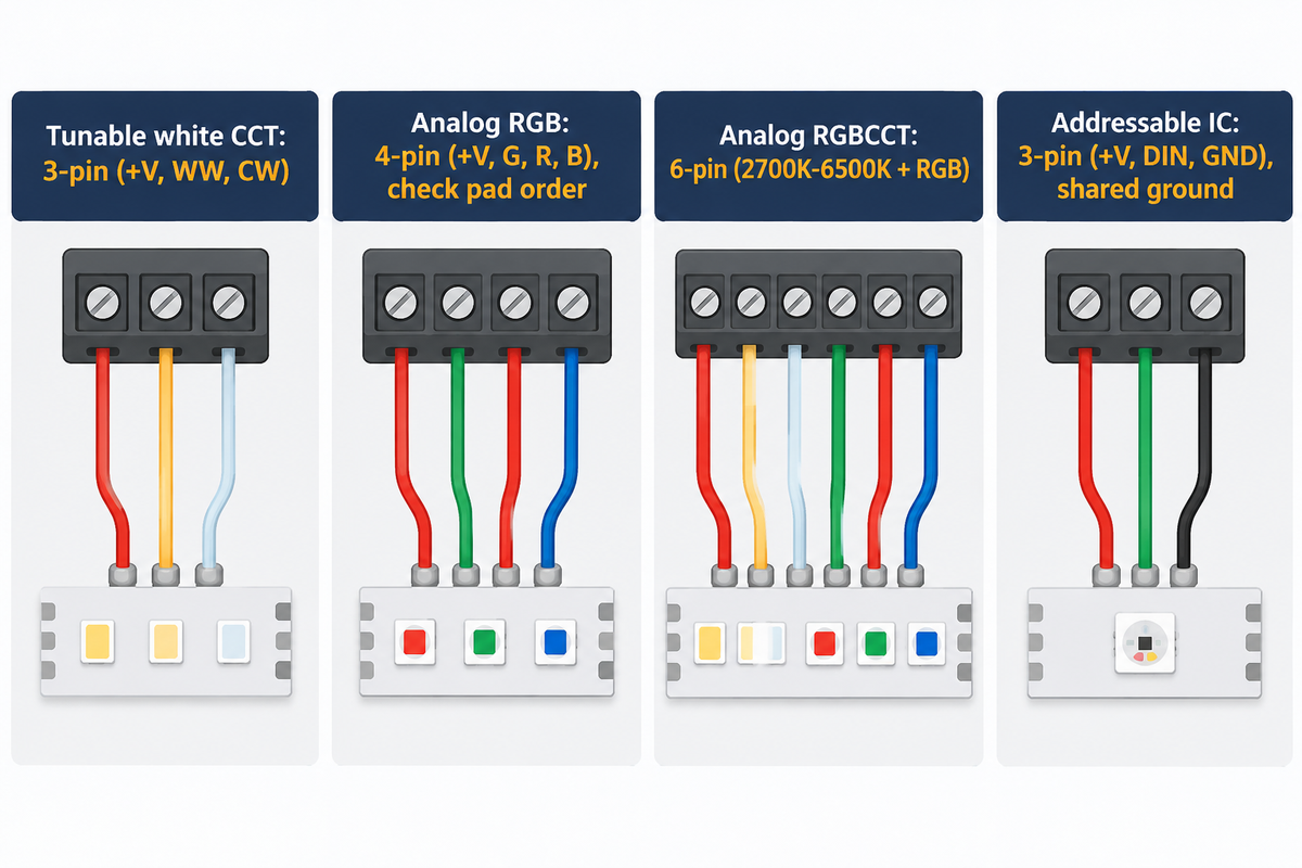
Connect the LED controller between the constant-voltage DC power supply and the light strip. Analog 4-pin RGB, 5-pin RGBW, and 6-pin RGBCCT strips wire common-anode +V plus each color channel (R, G, B, W, WW, CW) to matching terminals. Digital addressable strips must follow the printed DIN → DOUT arrow.
Connecting RGB or tunable-white leads straight to a DC supply locks every diode full-on with zero color control. SuntechLite says that RGB and RGBW strips typically use a 10-12 mm PCB. Five-color RGBCCT strips combine R, G, B, warm white, and daylight white (2700K–6500K on 5050 SMD LEDs) on a wider 12–15 mm PCB. Pin labels differ between vendors even for the same color format. Check pin labels before ordering: some vendors use “RGBWW” to describe 5-pin RGB and Warm White tape, and others use that same description to mean 6-pin RGBCCT. Compare color systems in our guide to RGB, RGBW, RGBWW, and addressable RGBIC strip architectures.
Addressable pixel strips (usually 8, 10 or 12 mm wide, reaching 20 mm on high-current UCS2903 tape) replace separate color wires with digital data. Tie controller ground and power supply -V together on a common reference, and feed data into the DIN pad. Inject DC power from the supply for multi-reel pixel runs, so load current bypasses the controller PCB. Large commercial projects can pair DMX512 controllers for multi-zone LED installations with constant-voltage LED controllers and signal repeaters.
| Strip Type | Pins | Typical Pad Labels | Typical PCB Width | Wiring Rule at Controller |
|---|---|---|---|---|
| Single-color dimmer | 2-pin | +V, -V | 8 mm – 10 mm | Inline PWM dimmer sits between PSU DC out and strip |
| Tunable white (CCT) | 3-pin | +V, WW, CW | 8 mm – 10 mm | Shared +V anode; controller modulates WW and CW negatives |
| Analog RGB | 4-pin | +V, G, R, B (or R, G, B) | 10 mm – 12 mm | Read pad letters—many reels print G-R-B rather than R-G-B |
| Analog RGBW | 5-pin | +V, R, G, B, W | 10 mm – 12 mm | Use true 4-channel RGBW controller so dedicated W chip fires |
| Analog RGBCCT | 6-pin | +V, R, G, B, WW, DW | 12 mm – 15 mm | Requires 5-channel controller (2700K–6500K + RGB) |
| Single-wire IC (WS2812B / WS2811) | 3-pin | +5V (WS2812B) or +12V (WS2811), DIN, GND | 8 mm – 12 mm | Single-wire data into DIN only; share GND between controller and PSU |
Connecting LED Strip Lights to a Wall Switch, Dimmer, or Commercial Control System
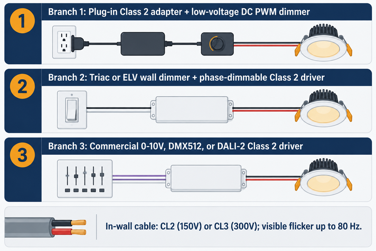
Wire an AC phase-cut wall dimmer only to a Listed Triac/ELV dimmable Class 2 driver, or feed an unswitched AC power source to a 0-10V or DALI dimmable driver. Concealed in-wall Class 2 low-voltage wiring requires CL2 or CL3 jacketed cable under NFPA 70 (NEC) Article 725.
Wall dimmers in series with non-dimmable power bricks can starve the power bricks’ switching regulators and lead to buzz or strobe. ENERGY STAR’s fixture guidance notes that not every LED works with every dimmer switch and suggests published compatibility lists. Non-IC-rated housings require at least 3 inches of clearance from thermal insulation. The U.S. Department of Energy states:
“If the light is changing in output up to 80 Hertz, which means it’s going on and off, or from a high level to a low level, 80 times a second, that is called ‘visible flicker’.”
The Department of Energy adds that 80–2,000 Hz oscillation creates stroboscopic motion artifacts, and mismatched dimmers can drive LED flicker to 100 percent from on to full off. For commercial lighting solutions, see our guide on matching a 0-10V dimmer to constant-voltage LED drivers. Review the insulation of primary and secondary conductors against AC line and DC low voltage color codes.
Do I need an electrician to install LED strip lights?
Plugging a Listed Class 2 adapter into an existing indoor outlet and surface-mounting low-voltage leads doesn’t require the services of an electrician. Splicing AC mains branch wiring inside junction boxes, adding new wall switches, and fishing concealed cables inside walls and ceilings require a licensed electrician.
During LED strip installation, low-voltage wiring is still subject to fire safety laws. Silver Fox Labeling’s NEC Article 725 guide states that CL2 (150V) and CL3 (300V) cables are flame-tested for wall cavities. CL2P should be used for air plenums and CL2R for vertical risers. Plug-in adapter cords should never be run behind drywall. Match your room setup using the 3-Branch Power & Control Routing Tree below.
3-Branch Power & Control Routing Tree
1. For switched outlets or countertop plug-in kits (DIY), plug a Listed Class 2 adapter into an accessible receptacle. Put an inline RF, Zigbee, or rotary PWM dimmer on the low-voltage DC side.
2. For residential wall dimmer switches, wire a compatible Triac or ELV wall dimmer on the AC line feeding a Listed phase-dimmable Class 2 driver.
3. For commercial multi-zone dimming, feed unswitched AC power to Class 2 drivers equipped with 0–10V, DMX512, or DALI-2 control inputs, matching control-wire insulation ratings to the enclosure.
Waterproofing Cut Connections, Mounting Surfaces, and Heat Dissipation
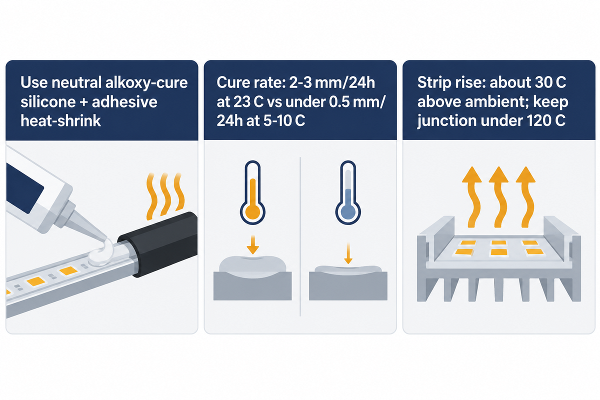
Reseal cut IP65 or IP67 outdoor LED strip ends with neutral alkoxy-cure electronics silicone sealant inside a silicone end cap, plus adhesive-lined heat-shrink tubing. Allow at least 24 hours of cure at room temperature, and longer in cold or dry air. Mount high-output strips in aluminum channels instead of directly to raw wood.
Slicing a waterproof sleeve exposes bare copper where rainwater wicks inward, and ordinary bathroom caulk attacks that joint chemically. Both RH Strip Lighting and Kingdeli’s sealant guide warn that acetoxy-cure RTV silicone releases acetic acid (vinegar smell) while curing, corroding copper and tin. Kingdeli’s guide shows how sharply silicone cure slows in cold, dry air: acetoxy-cure sealant drops from 2–3 mm/24h at 23°C and 50% relative humidity to below 0.5 mm/24h at 5–10°C and 20% relative humidity.
Posters on the EEVblog electronics forum warn that neutral, oxime-cure silicones release ketoximes that still corrode bare copper on direct contact. Neutral alkoxy-cure (alcohol-releasing) silicone does not attack copper, while hot glue peels off smooth jackets within a few years. Field resealing these joints with an alkoxy-cure silicone and an adhesive heat-shrink will protect the joints against outdoor splashes and rain. Field splices don’t reinstate the original factory ingress rating. Continuous underwater use requires a factory-sealed IP68-rated product, such as factory-molded silicone neon flex.
Measure strip thickness first, because the profile must fit the strip’s height for you to install your LED strip cleanly. SuntechLite lists overall strip height at ~1.5 mm for IP20, 2–3 mm for IP65 coated tape, and 5–8 mm for IP68 sleeves. Those strips sit on 0.24 mm or 0.35 mm flexible PCBs built with 2 oz or 3 oz copper. Wipe the mounting surface clean and dry with isopropyl alcohol before pressing down the 3M adhesive (double-sided adhesive backing). Add screw-in mounting clips or an aluminum bracket when securing heavy strip lights on a wall or soffit.
Do LED strip lights get hot?
Yes, LED strip lights get warm in normal service, with Waveform Lighting reporting quality underdriven strips rising about 30°C (55°F) above ambient in free air. Never run LED tape coiled in its plastic reel. Mild, even warmth is normal. One hot spot indicates a bad contact.
During commissioning, even heat along the strip is normal, while a single scorching clip means a failing connection. High-density strips last longer inside an aluminum extrusion, whose metal surface area draws heat away from LED junctions (rated 120°C max per RH Strip Lighting) and preserves adhesive grip. Replace any hot clips or solder the pads directly.
Pre-Mount Bench Test and Troubleshooting Dead Sections, Wrong Colors, or Flicker
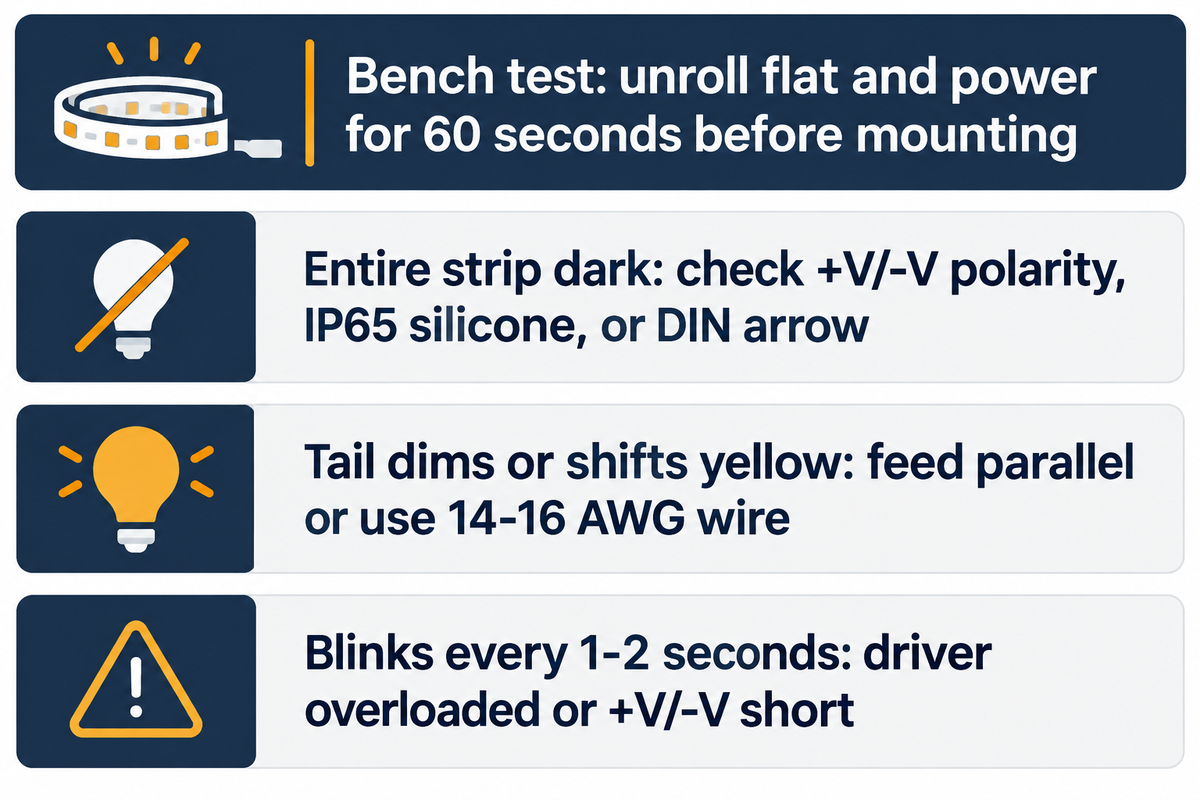
Unroll every reel flat on a workbench and power the full system for 60 seconds before peeling the adhesive liner. Confirm a reading of the rated DC output across +V and -V pads with a multimeter. Find a reversed connector on the bench and you’ve saved a finished cabinet from adhesive tear-out.
Energize the feeder cable first and probe +V and -V polarity with a DC voltmeter before landing any power-injection tee onto the strip. Reversed injection leads create a dead short across the operating circuit, and repeated clip reconnections in humid air increase contact resistance. For whole room dimmer strobing, see our article on diagnosing driver-induced LED flickering and run the 5-Symptom Fault Isolation Ladder below.
| Observed Symptom | Most Likely Electrical Cause | Multimeter / Visual Check | Direct Fix |
|---|---|---|---|
| 1. Entire strip stays dark | Reversed +V/-V polarity, unpeeled IP65 silicone, or DIN/DOUT reversal | Probe DC volts at driver out, then on bare copper pads past first clip | Flip strip + to +, scrape clear silicone off pads, or feed DIN arrow side |
| 2. Strip stops lighting after splice or cut | Off-mark scissor cut or narrow strip misaligned inside wider clip | Measure continuity across splice prongs and inspect cut line | Trim back to next valid copper pad pair and re-terminate |
| 3. Tail dims or shifts yellow/pink | Excessive daisy-chain length or undersized 20–22 AWG feeder cable | Compare feed-end pad voltage against tail pad voltage under load | Split into parallel home-runs or inject power via 14–16 AWG wire |
| 4. RGB remote buttons show wrong colors | Pin sequence mismatch (+V-G-R-B strip wired as +V-R-G-B) | Read tiny letters printed beside copper pads vs controller terminals | Swap G and R leads at controller block or remap channel order in app |
| 5. Whole run blinks every 1–2 seconds (“hiccup”) | Driver loaded past rated wattage or solder whisker shorting +V to -V | Disconnect half the strip load or check pad resistance with power off | Clear stray wire strand or split load across a second Class 2 driver |
Frequently Asked Questions
Can you connect two different brands of LED strip lights together?
Yes, LED strip lights from different manufacturers can be joined, but only if both reels match in DC operating voltage, PCB width, pin count, and pad pinout order. Even on matching 4-pin RGB strips, one vendor often prints +V-G-R-B while another uses +V-R-G-B. It is best to check the color temperature of the diodes and lumen output per meter prior to use to minimize any color irregularities.
Do LED strips run up the electric bill when left connected?
No, a 5-meter strip drawing 24 W for 6 hours daily uses 0.144 kilowatt-hours per day (52.56 kilowatt-hours yearly). This level of consumption is much less than that of halogen rope lights. Total energy cost scales directly with strip wattage, run length, and daily operating hours, plus a small continuous standby draw whenever a smart Wi-Fi or Bluetooth controller stays energized.
Should LED strips go in front or back of a cabinet shelf?
Mount under-cabinet LED strips 1-2 inches behind the front underside lip in a frosted aluminum channel rather than against the rear wall. A front lip mount placement reduces glare on counter tops, provides even lighting of the prep zone, and removes hotspots along backsplashes.
Can you connect LED strip lights without a connector or soldering?
No, taping bare wires onto flat copper pads loosens and arcs; always solder leads or lock a matched clip connector.
Can non-waterproof IP20 LED strip lights be installed outdoors if placed inside an aluminum channel?
No. An uncoated IP20 strip enclosed in a snap-on aluminum diffuser channel does not weatherproof a fixture for outdoor exposure. Rain, night air, and morning condensation seep through the mitered corners, end caps, and wire holes, and oxidize bare copper pads and corrode surface-mounted resistors within months. Outdoor soffits, decks, and facades require IP65 or IP67 strips and a weatherproof NEMA or IP66 enclosure around the Class 2 driver. Seal every cut termination with neutral alkoxy-cure electronics silicone plus dual-wall adhesive-lined heat-shrink tubing so moisture cannot wick along stranded leads.
What happens if you connect a 12V LED strip to a 24V power supply?
Double voltage will cause excess current to flow through resistors and diodes, resulting in blinding flash output, overheating, and permanent burnout.
Planning an architectural cove, retail display, or commercial lighting rollout? Zhongshan Guangqi Lighting Co. Ltd supplies architectural and commercial LED luminaires alongside commercial constant-voltage LED drivers and signal controllers. Confirm strip wattage per meter, PCB width, UL 2108 / Class 2 driver markings, and dimmer compatibility on your submittal sheet before ordering.
References & Sources
- LED Basics, Solid-State Lighting U.S. Department of Energy (DOE)
- US8714772B1: LED Strip Light Connector System United States Patent and Trademark Office (Assigned to Inspired LED LLC)
- ANSI/UL 2108 Edition 2: Standard for Low Voltage Lighting Systems (Revised Sept 27, 2024) UL Standards & Engagement
- UL Question Corner: Low Voltage LED Luminaire Drivers International Association of Electrical Inspectors (IAEI Magazine)
- NFPA 70: National Electrical Code (NEC) Articles 411 & 725 National Fire Protection Association
- Light Fixtures Installation & Dimmer Compatibility Guidance U.S. Environmental Protection Agency / ENERGY STAR
- Flicker Basics, Solid-State Lighting U.S. Department of Energy (DOE)