Get in Touch with GUANGQI


How to Choose a DMX Controller for LED Lighting

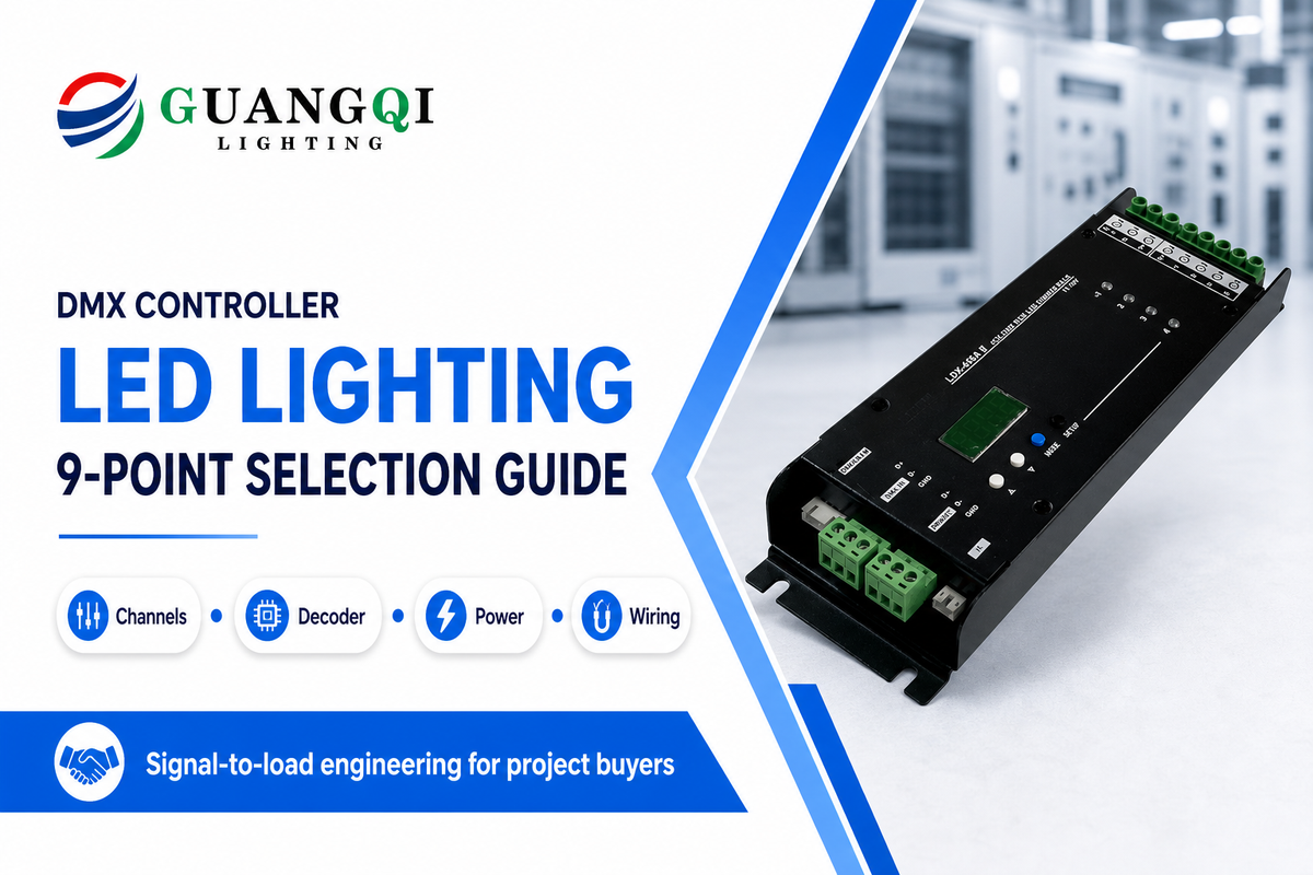
A DMX controller for LED lighting is a transmitting device that sends digital channel values to compatible fixtures or decoders. Selection starts with the signal path, not the fader count. A fixture or decoder interprets the control data; an LED driver and power supply carry the electrical load. Treating those jobs as interchangeable is how a system can pass a 512-channel check and still flicker, lose fixtures, or fail to light.
Updated July 2026. Reviewed by the Zhongshan Guangqi Lighting Co., Ltd. technical team.
Quick Specs: freeze these before selecting a controller
- Control capacity: fixture quantity × active channel footprint, plus planned reserve.
- Physical link: receiver unit loads, cable route, isolation, splitter locations, termination, and test access.
- Load stage: analog PWM or pixel protocol, output voltage, current per channel, total watts, and power-supply headroom.
- Transport: native DMX, Art-Net, sACN, or a wireless bridge, with ownership and failure behavior defined.
- Handover: address schedule, scene file, loss-of-signal state, RDM compatibility, and measured commissioning results.
Short answer: size the DMX controller by data slots and operating workflow, then approve the decoder, driver, power supply, cabling, isolation, and network as separate system layers. The controller specification alone can’t prove LED-load compatibility.
DMX Controller, Decoder, Driver: Follow the Signal Path
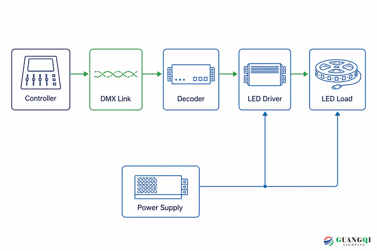
Commands originate at the controller. Inside a fixture, driver, or separate decoder, the DMX receiver reads the assigned data slots. Downstream output circuitry then regulates the LED load. In an analog RGBW strip system, that output is commonly four pulse-width-modulated channels. Pixel systems may instead translate DMX into a specific serial protocol. Neither job means the console is supplying the LED power.
Under ANSI E1.11-2024, controllers are transmitting devices and controlled equipment contains receiving devices. That distinction is more than terminology: the DMX conductors carry control data, while the LED circuit must be engineered for its own voltage, current, conductor size, protection, and thermal conditions. The U.S. Department of Energy’s guidance on color-tunable LED products likewise distinguishes the control signal from luminaire power.
Hidden risk appears when a buyer approves only the console because the signal path looks simple. Picture a 50-fixture facade: a valid data packet can reach every receiver while an incompatible decoder output or undersized 24 V circuit causes failure at the load. Guangqi engineers therefore ask for the fixture schedule, decoder schedule, and full-load calculation as separate evidence before a project configuration is confirmed.
Translate buyer vocabulary into functions. A light strip catalog may use DMX control, LED DMX, DMX lighting controls, DMX signal, DMX system, LED color controller, accessory, LED decoder, or DMX512 controller as overlapping labels. None identifies the complete communication protocol or proves how a dimmer controls lighting fixtures, multiple lights, and brightness. Request the signal-path diagram instead of accepting the label.
| Stage | What it proves | What it does not prove |
|---|---|---|
| Controller | Scenes, timing, universes, user interface | LED voltage or output current |
| DMX link | Data reaches addressed receivers | That receivers can drive the connected load |
| Decoder or fixture receiver | DMX data becomes a local control output | Power-supply capacity or voltage-drop margin |
| Driver and power supply | Electrical delivery to the LED load | Addressing, scenes, or network redundancy |
For a commercial shortlist, start with the DMX and LED controller range, but request a block diagram for the exact project. Merely labeling a product “DMX compatible” doesn’t create a complete signal-to-load specification.
What is the difference between a DMX controller and a decoder?
Controllers compose and transmit channel values. Decoders receive those values and convert them into outputs an LED product understands. Some luminaires contain their own receiver and driver, so no external decoder is needed. Constant-voltage LED tape usually needs a separate decoder matched to its color channels and electrical load.
Calculate Channels, Addresses, and DMX Universes
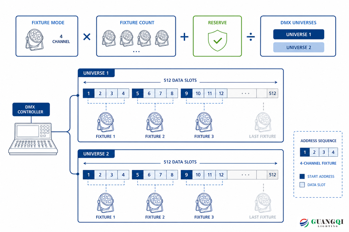
One DMX512 universe carries up to 512 data slots. Slot 0 is the START Code; the controllable data positions are slots 1 through 512. Each fixture may use more than one slot. Its active personality or mode may use three slots for RGB, four for RGBW, six for tunable-white with additional functions, or dozens for a feature-rich luminaire.
The 512-Channel Headroom Rule
- Take the channel footprint of the selected fixture mode.
- Multiply by the number of independently controlled fixtures or zones.
- Add an agreed reserve for future zones and mode changes.
- Divide by 512 and round up to obtain the universe count.
- Confirm that no fixture footprint crosses a universe boundary unless the product and controller workflow explicitly support that patch.
Worked example: 50 independently controlled RGB fixtures × 3 slots × 1.20 reserve = 180 planned data slots. That fits one universe and leaves 332 data slots unused. Reserve percentage is a planning policy, not an ANSI requirement; select it according to the project’s change risk. Use the public DMX universe calculator to test other fixture modes.
A common planning mistake is to divide 512 by the fixture count before fixing the mode. Calculation fails because a 4-channel RGBW personality and a 16-channel effects personality consume very different footprints. In practice, Guangqi’s calculator keeps the 20% reserve visible so the buyer can distinguish a project assumption from the 512-slot standard limit.
Addressing must follow the channel footprint. If one RGBW fixture starts at address 1 and uses four slots, the next independent fixture normally starts at 5. Giving two fixtures the same starting address can be intentional when they should mirror each other. It’s a fault only when independent control was required.
Channel arithmetic is only the logical layer. Even a one-universe controller may need several isolated output branches because the physical DMX line has its own receiver-load and routing limits.
Match the Decoder to RGB, RGBW, Tunable White, or Pixel LEDs

Start at the LED product, then work backward. Identify whether it’s constant voltage, constant current, or digitally addressable. Record its nominal voltage, maximum load, color architecture, common-anode/common-cathode arrangement where relevant, and pixel chip/protocol. Only then can a decoder be selected.
Choosing the wrong output stage creates a predictable failure: data appears healthy, yet colors are swapped, pixels don’t respond, or a channel trips under load. Its root cause is structural because analog PWM and serial pixels encode control differently. For example, a 24 V RGBW tape zone needs four matched analog outputs, whereas a pixel facade needs a documented chip protocol and port capacity. Guangqi’s project review confirms those details against the exact LED product rather than treating every “RGB controller” as equivalent.
RGB terminology also needs normalization. Phrases such as RGB LED light, channel DMX decoder, LED RGB, channel DMX512, and RGB light may describe different output stages. “Dim” can mean master intensity, per-color PWM, or a fixture function. Match the exact manual, voltage, channel order, and pixel protocol before assigning an address.
| LED load type | Typical control stage | Minimum checks | Not suitable when |
|---|---|---|---|
| Single-color tape | 1-channel PWM decoder | Voltage, current, PWM frequency | Incompatible with a constant-current load |
| Tunable white | 2-channel or product-specific decoder | CCT mixing logic and channel mapping | Redundant when a digital driver is integrated |
| RGB tape | 3-channel constant-voltage decoder | Common conductor, per-channel and total current | Independent pixel effects are required |
| RGBW tape | 4-channel constant-voltage decoder | White-channel load and scene mapping | Reject an output limited to RGB |
| RGB+CCT | 5-channel decoder | Combined-load limit and personality | Unsuitable for per-pixel addressing |
| Constant-current module | DMX constant-current driver | Output current, voltage window, dimming curve | Only a constant-voltage decoder is offered |
| Addressable pixel | Protocol-matched DMX-to-SPI gateway | Chip type, pixel count, frame rate, port limits | Gateway protocol is not documented |
| DMX-native fixture | Integrated receiver/driver | Personality, footprint, termination, loss state | Load requires an external analog output |
| Long analog tape run | Distributed decoders and power injection | Voltage drop at full white and conductor size | One remote decoder would exceed cable limits |
| Facade pixel system | Network backbone plus local gateways | Universes, synchronization, redundancy, IP rating | One native DMX line cannot cover the topology |
Guangqi’s DMX512 and SPI pixel lights illustrate why “digital LED” is still not a complete protocol description. Controller, gateway, and pixel product must agree on the wire protocol and capacity. For analog loads, verify the power and voltage-drop calculation independently.
Can a DMX controller control addressable LED strips?
Yes, when a compatible gateway translates DMX or an Ethernet lighting protocol into the exact pixel protocol used by the strip. Confirm the supported chip family, pixels per port, refresh rate, universe mapping, cable distance, and fault behavior. Generic three- or four-channel PWM decoders can’t create per-pixel effects.
A 512-Channel Controller Does Not Size the Power Circuit

Spare conductors in a DMX cable are signaling conductors, not a fixture power feed. Logical capacity and electrical capacity therefore need separate approvals. Even a 512-data-slot source may control many zones while delivering no LED-load power at all.
Engineering note
Check the worst electrical scene, not the average animation. Full-output white can load RGBW channels very differently from a saturated color scene. Measure voltage at the remote load and temperature at the decoder and power supply under the agreed test condition.
For each decoder zone, record input voltage, output architecture, rated current per channel, total device limit, ambient-temperature derating, protective devices, and cable ampacity. Then calculate the connected LED load and voltage drop. If PWM quality matters to cameras or sensitive occupants, assess the output with the LED PWM flicker risk indicator and verify the actual hardware.
A measured acceptance sheet turns those labels into evidence. For example, one qualified 24 V mock-up might record 23.4 V at the remote load, 3.2 A total current, 75 W input, 25 °C ambient, 58 °C case temperature, 1 kHz PWM, a 40 m power route, a 120 m DMX branch, and 2.6% voltage drop. A second 12 V zone might record 11.6 V, 4.0 A, 46 W, 30 °C ambient, 2 kHz PWM, a 20 m route, and 3.3% drop. Compare response at 25%, 50%, and 100% dimming to reveal curve or flicker problems, then repeat the 50% point after thermal stabilization. These figures are illustrative fields, not universal limits; the approved values must come from the selected hardware, conductor calculation, and project environment.
Overload can hide behind a correct channel schedule. It happens because data-slot capacity is unrelated to a decoder’s watts or amperes. On a 50-fixture installation, full white may expose a supply or conductor problem that colored scenes never reveal. Guangqi’s engineering review uses the connected load, measured remote voltage, and ambient condition to qualify the power stage instead of inferring capacity from the DMX label.
One practical failure pattern is “DMX indicator active, LEDs dark.” That can mean the data path is healthy while the power supply is off, polarity is wrong, the decoder output type is incompatible, a channel fuse is open, or the LED load exceeds protection limits. Troubleshoot data and power as parallel paths instead of repeatedly changing addresses.
Cable, Connector, Daisy Chain, and Termination

ETC’s DMX512 engineering guidance recommends a daisy chain from device to device and warns against passive Y-splitting. When branches are required, use an active, preferably isolated splitter designed for DMX and RDM if bidirectional management is planned. The visual star of building cable is acceptable only when an active distribution device creates compliant branches.
When a specification says “DMX controller cable,” translate that phrase into measurable requirements: characteristic impedance, capacitance, shielding, conductor size, connector pinout, installed length, and receiver loading. A retail product name alone doesn’t establish the performance of the completed route.
In the preferred topology, where the transmitter sits at one end of the line, terminate the far end between Data+ and Data− with the specified nominal 120-ohm impedance. If the transmitter isn’t at an end, the standard calls for termination at both ends. Don’t scatter terminators across intermediate fixtures.
Do
- Use low-capacitance, impedance-appropriate twisted-pair cable.
- Document pinout at every connector transition.
- Place isolated splitters at branch and service boundaries.
- Label the last device and terminator on each branch.
- Test with the final installed cable route.
Don’t
- Assume any microphone cable is acceptable.
- Use a passive Y-cable as a permanent branch.
- Bond connector shell and signal common by habit.
- Count 512 data slots as 512 physical receivers.
- Assume legacy splitters pass RDM return traffic.
ESTA’s 2008 Recommended Practice for DMX512, reprinted in 2012, permits up to 32 unit loads on a line and recommends limiting lines to about 300 m, particularly when multiple devices are connected. Treat this as conservative installation guidance rather than a newly issued 2026 requirement. Each receiver may represent less or more than one traditional unit load, so use the manufacturer’s declared loading rather than counting housings.
Installation risk appears as intermittent failure rather than a neat on/off fault because reflections, common-mode voltage, cable loss, and receiver loading interact. For a 300 m branch serving several facade zones, the right call may be a certified isolated splitter placed earlier in the route. Guangqi’s branch review asks for the final cable and receiver schedule, not merely a line drawn between controller and lights.
Can microphone cable be used for DMX lighting?
Microphone cable may appear to work on a short bench test, but that isn’t an approval. DMX requires cable suited to its differential digital signaling. Capacitance, impedance, shielding, length, connectors, and the number of receivers all affect margin. Specify appropriate data cable and test the installed route rather than relying on an audio-cable label.
Choose Native DMX, Art-Net, sACN, or Wireless Transport

Native DMX, Art-Net, sACN, and wireless DMX solve different transport problems. Native DMX is a serial field link. Art-Net and sACN carry lighting data across an IP network to nodes that generate local DMX outputs. Wireless DMX replaces part of the data route with radio, but fixtures and gateways still need power.
DMX lighting controller software or a mobile app may improve scene editing, but both still depend on an interface or network node that produces the required field signal. Confirm what continues to run if the phone, computer, or cloud account is unavailable.
Tradeoffs become visible on a campus-scale application: four universes and a remote building can exceed the practical simplicity of native 300 m branches. Risk then moves into switch configuration, multicast, node recovery, or RF coverage because the network becomes part of the lighting system. A qualified control-system design should name who owns those settings and how the system is tested after a power or network failure.
Compare wireless DMX options and wired and wireless DMX as transport choices, not feature badges. A signal amplifier does not create another universe, while automation software does not replace the field interface. ArtNet, an XLR branch, a controller panel, or a 32 channel device each describes a different boundary. Likewise, a quoted 100m or 328 ft range must be tested on the installed route.
| Transport | Best fit | Evidence to request | Main limitation |
|---|---|---|---|
| Native DMX | Local, modest-universe branches | Topology, loading, termination, isolation | Serial branch and distance constraints |
| Art-Net | Multi-universe Ethernet distribution | Version, node mapping, broadcast/unicast plan | IP network must be engineered and owned |
| sACN | Managed standards-based streaming networks | Multicast, IGMP, priorities, source behavior | No substitute for switch and multicast planning |
| Wireless DMX | Temporary, movable, or cable-inaccessible links | RF survey, bands, latency, recovery, redundancy | Obstructions, people, reflections, and interference |
Gary Fails of City Theatrical explains that objects, people, reflections, and interference reduce wireless range. Published open-air range is not a fixed-installation guarantee.
For permanent facade projects, compare a wired backbone and local nodes against wireless only after an RF survey and a documented fallback plan.
NIST’s Industrial Wireless System team published a new electromagnetic-interference measurement dataset in February 2025. It doesn’t certify wireless DMX, but it supports treating interference as a measurable site condition rather than relying on an open-air range label.
Use the lighting control protocol selector to frame the choice, then require the network designer to own addressing, switch configuration, multicast behavior, cybersecurity boundaries, time synchronization where required, and recovery after a controller or link restart.
Integration, Commissioning, and Failure Isolation

Commissioning should prove behavior, not just demonstrate one colorful scene. Freeze the final personality and address schedule first; a later fixture-mode change can move every downstream address. Keep the controller project file, firmware versions, network map, decoder schedules, and branch drawings under revision control.
DMX controller programming is therefore part of system handover, not a private installer task. Whether the project uses a compact programmable DMX controller or a networked console, the owner needs the editable source file, backup, patch list, credentials, and a documented restore test.
- Verify equipment identity. Match model, firmware, personality, output type, and declared DMX/RDM behavior.
- Inspect the physical route. Confirm cable, pinout, branch isolation, shield treatment, unit loading, and termination.
- Patch one branch at a time. Prove address and channel response before enabling the complete system.
- Test full-load scenes. Run full white and high-current transitions while measuring remote voltage and temperature.
- Test data loss. Record whether each device holds last look, fades, blacks out, or enters a configured scene. ANSI E1.11 allows manufacturer-declared behavior; it is not universal.
- Test restarts. Power-cycle controller, gateways, switches, splitters, decoders, and supplies in realistic sequences.
- Test isolation boundaries. Look for flicker or receiver faults when equipment is supplied from different services or ground potentials.
- Capture handover evidence. Save measurements, screenshots, scene files, address schedules, fault tests, spares, and recovery instructions.
| Symptom | Check first | Next isolation step |
|---|---|---|
| No fixtures respond | Controller output and pinout | Test first receiver with a known-good short cable |
| Only downstream fixtures fail | Last working device and through connection | Bypass the suspect receiver |
| Random flicker | Termination, cable, shielding, ground loop | Shorten branch or insert an isolated splitter |
| Wrong colors | Personality and channel order | Test each decoder output separately |
| DMX LED active, load dark | Power, polarity, fuse, output type | Connect a known-good matched load |
| Works until full white | Supply capacity and voltage drop | Measure at the remote load under full output |
| DMX works, RDM discovery fails | Every splitter and in-line device | Bypass non-RDM infrastructure |
| Fails after network restart | IP, multicast, source priority, node boot | Replay the documented startup sequence |
| One service area affects another | Isolation and common-mode voltage | Separate branches with an isolated splitter |
For fixed architectural work, test representative LED wall washers and pixel products before mass installation. A mock-up catches personality, dimming, cable-entry, connector, thermal, and color-order problems while access is still easy.
Use the 9-Point Signal-to-Load DMX Fit Matrix

Use this matrix to compare quotations on the same basis. A blank cell isn’t a promise to resolve later; it’s an open engineering item. Attach the completed matrix to the purchase specification and commissioning plan.
| No. | Decision point | Evidence to freeze | How to verify | Reject if |
|---|---|---|---|---|
| 1 | Fixture personality | Mode and slot footprint | Manual plus bench patch | Only “DMX compatible” is stated |
| 2 | Channel reserve | Base slots and reserve policy | Recalculate schedule | No future capacity is documented |
| 3 | Universe architecture | Universe, port, gateway map | Review patch and node config | A footprint crosses an unmanaged boundary |
| 4 | Decoder output | Analog/pixel type and channel order | Test exact LED product | Protocol or polarity is ambiguous |
| 5 | Electrical capacity | Voltage, current, watts, derating | Full-load measurement | Only channel count is supplied |
| 6 | Physical DMX branch | Cable, length, unit load, splitters, termination | Drawing plus line test | Passive star or unknown loading |
| 7 | Transport and network | Protocol, addressing, switches, RF plan | Failure and restart test | Network ownership is undefined |
| 8 | Isolation and failure state | Port isolation, loss behavior, RDM chain | Service-boundary and data-loss tests | Behavior is assumed rather than declared |
| 9 | Handover evidence | Files, schedules, results, spares, recovery | Witnessed acceptance test | The quote ends at hardware delivery |
RFQ checklist
- Attach fixture schedules and selected personalities.
- Require a universe and address schedule.
- Require decoder output and full-load calculations.
- Require a branch drawing with splitters, isolation, unit loads, and terminators.
- Require Art-Net/sACN/RF configuration and recovery ownership.
- Require declared data-loss behavior and an acceptance-test script.
When the matrix is complete, send it with project conditions through the Guangqi Lighting project inquiry. That creates a more comparable response than asking only for “a 512-channel DMX controller.”
For a DMX controller for beginners, the same matrix can be shortened to four first checks: fixture mode, total data slots, decoder/load compatibility, and a correctly terminated cable branch. Scaling up should add evidence, not replace those basics.
When Not to Buy a DMX Controller

DMX is strong for synchronized scenes, dynamic color, and interoperable entertainment-style control. It isn’t automatically the best choice for every building or LED product. Reject a DMX-first design when another protocol better matches the operating requirement, the maintenance model, or the required building-system feedback. A protocol decision should follow the operating narrative rather than a product label.
Common assumptions fail when dynamic show control isn’t the real operating priority. In a 200-luminaire office or a simple local dimming application, maintenance feedback, building-system integration, or operator simplicity may matter more than rapid scene streaming. Guangqi can compare DMX512, DALI-2, 0-10V, and wireless options against the project narrative; the honest limitation is that no single protocol wins every use case.
Search terms from stage lighting control need the same boundary. Chauvet, Obey, PAR, stick, and Pi may point to a brand, console family, fixture form, handheld interface, or hobby computer. Their versatility or a promise of vibrant effects says nothing about fixed-installation isolation, load capacity, address records, or recovery behavior.
| Requirement | Consider instead | Why |
|---|---|---|
| Building-wide status and luminaire management | DALI-2 or an integrated building-control layer | Feedback and building workflows may matter more than show speed |
| Simple dimming with limited scenes | 0-10V or product-native control | Lower operational complexity can be preferable |
| Dense addressable pixels | SPI-native controller or media server with gateways | Pixel mapping and bandwidth dominate |
| One repeating local effect | Standalone fixture mode | Central control may add no useful operating value |
| Life-safety function | Code-compliant dedicated safety controls | DMX has no mandatory slot-data error checking for hazardous control |
Guangqi publicly supports DMX512, DALI-2, 0-10V, and wireless control families. Review the broader commercial lighting control systems rather than forcing the project into one protocol. For facade work, begin with the operating scenes, maintenance access, and integration boundary before selecting facade architectural lighting hardware.
Frequently Asked Questions
These answers follow the terminology and physical-link boundaries in ANSI E1.11-2024; individual product behavior still requires the selected fixture or decoder manual.
Do you need a DMX controller for LED lights?
Use one when fixtures or decoders need programmed scenes, precise timing, independent zones, or synchronized channel values. Some fixtures can run standalone auto, sound-active, or master/slave programs without a controller. Simple white-light dimming may fit 0-10V or another building-control protocol better. Define the required operator workflow clearly before selecting DMX.
What is the difference between a DMX controller and a DMX decoder?
The controller creates scenes and transmits channel values; the decoder listens to assigned data slots and converts them into local outputs. Those outputs might be pulse-width-modulated channels for RGBW tape or a serial stream for pixels. Some products combine receiver and driver functions, but the decoder’s voltage, current, total power, thermal rating, channel order, and loss-of-signal behavior must still match the connected LED load.
How many LED lights can one DMX controller run?
No universal fixture number exists. Multiply the active fixture footprint by the independently controlled fixture count, add the project’s reserve, and divide by 512 data slots. Then verify the physical branch separately. ESTA recommended practice permits up to 32 unit loads on a line, although modern receivers may declare fractional loading and active splitters create additional branches.
Can DMX lights work without a controller?
Some can run standalone or master/slave programs. Check the exact fixture manual for the available behavior.
Is wireless DMX reliable for architectural lighting?
It can be reliable when the RF environment, distance, antennas, receiver placement, redundancy, and recovery behavior are engineered. It is not a cable-free power solution, and published open-air range falls with walls, people, reflections, and interference. Permanent installations should compare wireless risk against a wired backbone and local nodes, conduct an occupancy-aware RF survey, test restart behavior, document the fallback state, and assign responsibility for future spectrum changes.
Can a DMX controller power LED strip lights directly?
Usually no. Most controllers send control data. The strip needs a compatible decoder or driver and a correctly sized power supply. A combined controller/decoder product may drive a load directly, but only within its documented voltage, per-channel current, total power, temperature, and wiring limits.
References & Sources
- ESTA, ANSI E1.11-2024, USITT DMX512-A
- ESTA, Recommended Practice for DMX512
- Electronic Theatre Controls, DMX512 Info
- RDM Protocol, What is RDM?
- Art-Net, Official protocol information
- City Theatrical, What is Wireless DMX?
- NIST, 2025 industrial wireless interference dataset update
- U.S. Department of Energy, Understanding LED Color-Tunable Products
- Google Patents, US8115407B2 address-free lighting driver
Related Guides and Tools
- LED controller types and wiring basics
- Channel and DMX universe calculator
- Controller power and voltage-drop calculator
- DMX, DALI-2, and 0-10V protocol selector
- LED pixel-light options for dynamic facades