Get in Touch with GUANGQI


Electrical Wire Color Codes: Standard AC, Three-Phase, DC Power, and Regional Wiring Identification

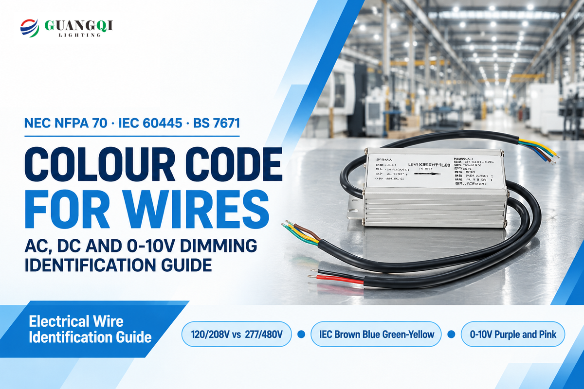
In North America, per NFPA 70, black, red, and blue are the colors used to identify 120/208V phase legs. White or gray wires are grounded neutrals, while equipment grounds are green or bare. Internationally, rules by IEC 60445 state AC phase conductors are brown, black, and gray, and blue is the color of a neutral wire, while protective earth is green-yellow. Pre-checking the wire color code before terminating a cable prevents dead shorts, blown drivers, and severe electrical shock.
Quick Engineering Summary (TL;DR):
- Across global standards, three primary conductor roles (Live/Hot, Neutral, and Protective Earth) are governed by NFPA 70 (US NEC) and IEC 60445:2021 up to 1,000 V AC.
- Watch for cross-border traps: Blue is a Phase C hot wire in US 120/208V panels, but it serves as a neutral wire under IEC 60445 and UK BS 7671. Gray is a 277V neutral in the US, yet it carries 400V Phase L3 power in Europe.
- Under the NEC 410.69 dimming change (effective January 1, 2022), factory-installed 0-10V dimming negative leads changed from gray to pink, paired with purple for positive.
- Per the NEC 200.6 and 250.119, field re-identification of single insulated neutral conductors in conduit is allowed only for wires 4 AWG and larger.
What Does the Electrical Colour Code for Wires Mean Across Standards?
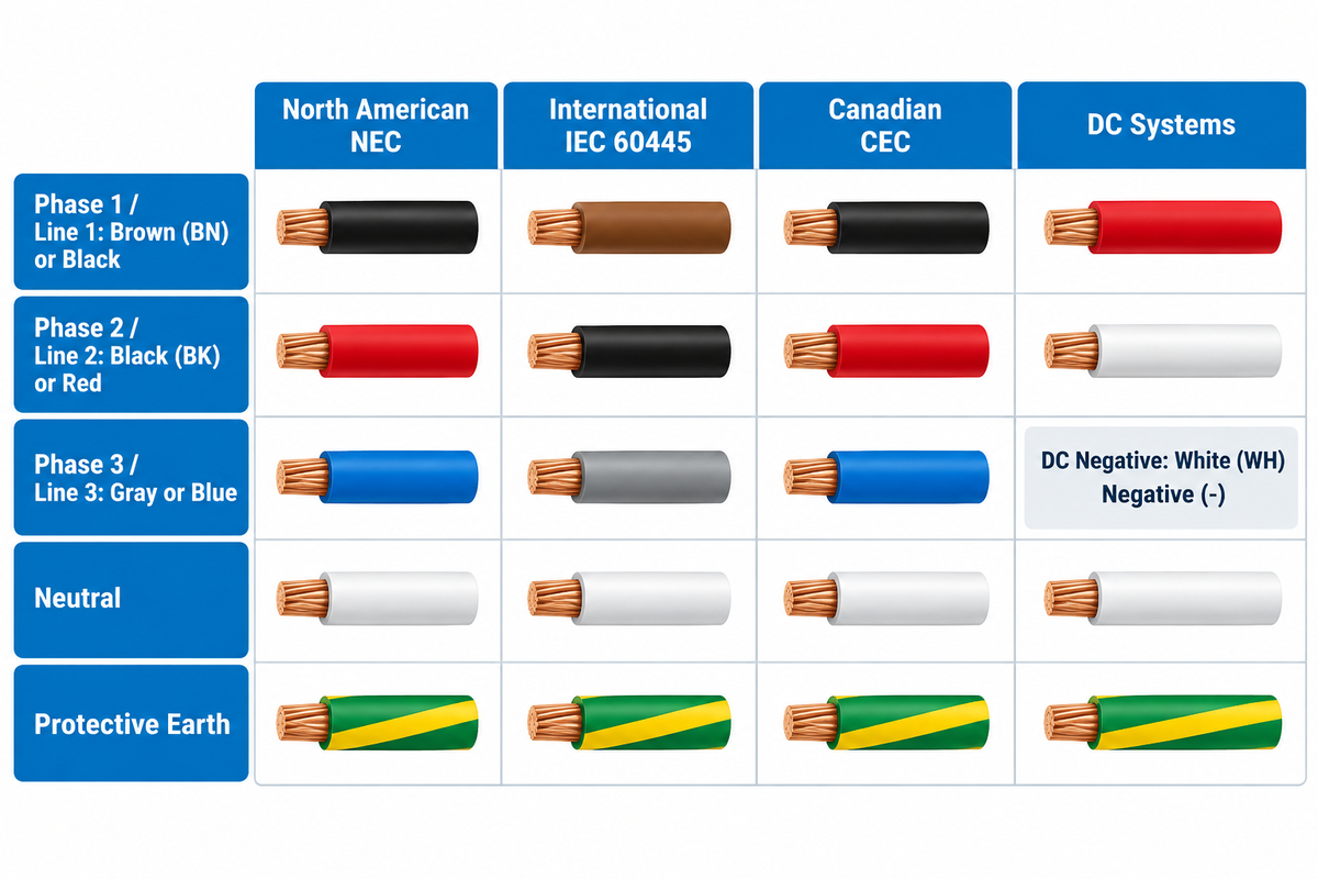
Electrical wiring colour rules assign specific colors to phase, neutral, and ground conductors so any electrician can trace circuit polarity at a glance. Since color code standards are significantly different between North America and international regions, assuming blue or black means the same thing in every electrical panel can energize a chassis or short a three-phase feeder.
This guide to electrical wire identification covers widely accepted industry standards for low-voltage AC and DC installations rated up to 1,000 V AC and 1,500 V DC. In the United States, NFPA 70 (the National Electrical Code) and federal OSHA 29 CFR 1910.304 govern workplace and building conductor identification. Across Europe, the United Kingdom, Australia, and most export markets, the International Electrotechnical Commission sets the standard for wiring through IEC 60445:2021 and its 2026 amendment, IEC 60445:2021/AMD1:2026.
Project teams working on export projects often source outdoor floodlights, street luminaires and pre-wired distribution boxes from Guangqi Lighting, a commercial outdoor LED lighting manufacturer. Adhering to the wiring colour scheme specified on the bill of materials, for the destination country, avoids costly field re-termination delays. Our Cross-Standard Phase & Neutral Translation Matrix below compares the exact insulation colour codes across the four most common global wiring systems.
| Circuit Function | US NEC (120/208/240V AC) | US NEC (277/480V AC) | IEC 60445 / UK Post-2004 (230/400V AC) | Canadian CEC (120/208V & 347/600V) | IEC 60445:2021 DC Power |
|---|---|---|---|---|---|
| Phase 1 / Line 1 (L1 / +) | Black | Brown | Brown (BN) | Red (L1) / Orange (347V) | Red (RD) Positive (+) |
| Phase 2 / Line 2 (L2 / -) | Red | Orange | Black (BK) | Black (L2) / Brown (347V) | White (WH) Negative (-) |
| Phase 3 / Line 3 (L3) | Blue | Yellow | Gray (GY) | Blue (L3) / Yellow (347V) | N/A (2-wire) |
| Neutral / Mid-Wire (N / M) | White (or Gray) | Gray (or White) | Blue (BU) | White | Blue (BU) Mid-Wire (M) |
| Protective Earth / Ground (PE) | Green, Green-Yellow, or Bare Copper | Green, Green-Yellow, or Bare Copper | Green-and-Yellow Stripe (GNYE) | Green or Bare Copper | Green-and-Yellow (GNYE) |
Single-Conductor Color Meanings: Black, Red, Brown, Blue, White, Gray, and Green-Yellow
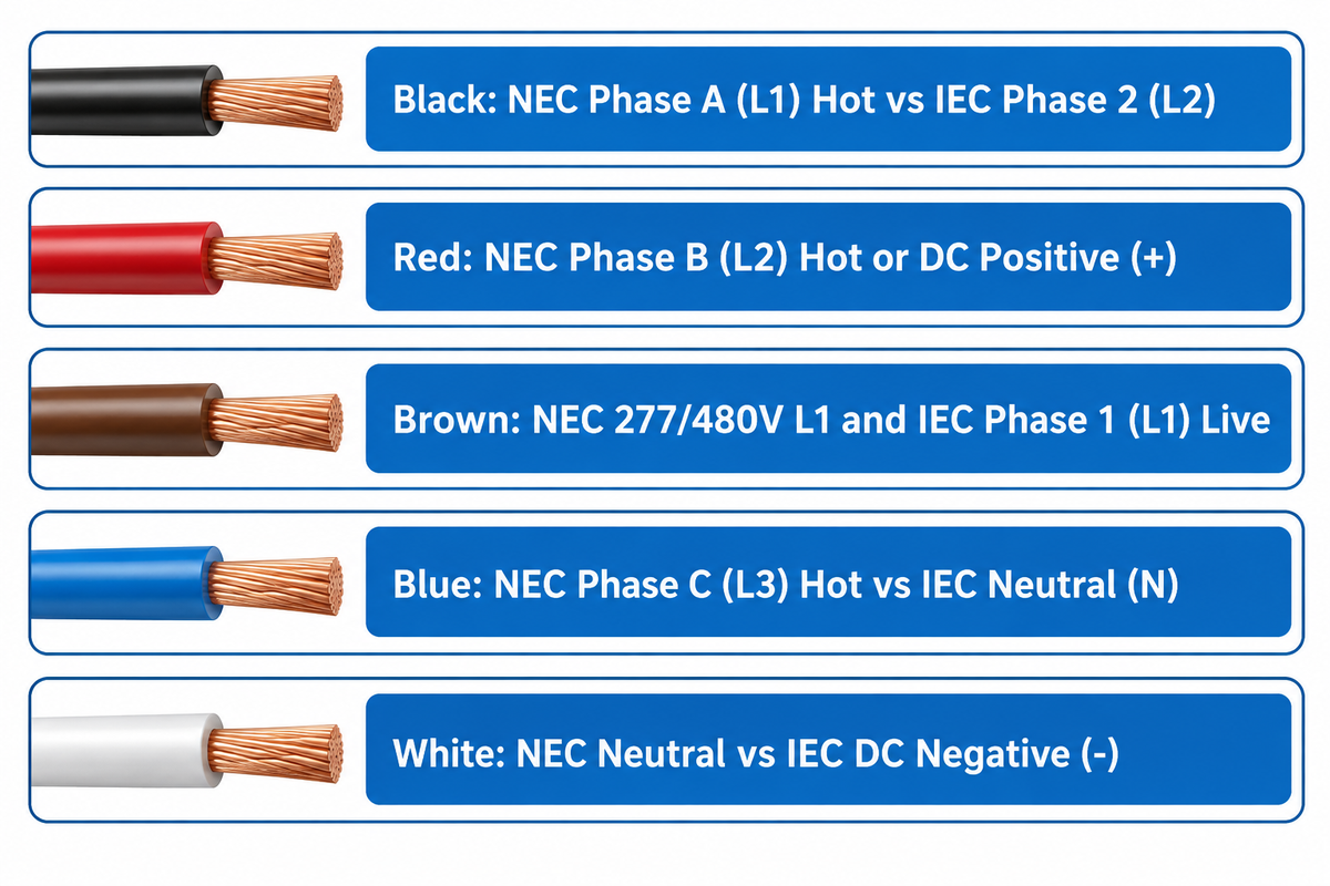
Opening a commercial junction box reveals different colored wires. Each electrical color represents a specific circuit duty and voltage level. Understanding individual colors and wiring color codes used in commercial buildings protects technicians before loosening a terminal. Under OSHA Standard Interpretation 1997-12-18-0 and 29 CFR 1910.304(a)(1), wiring diagrams can’t be a substitute for distinguishable grounded and grounding conductor identification when red wires pose a risk for confusion.
Among low-voltage AC branch and feeder circuits, 11 colors of insulation have standard meanings in NFPA 70 and IEC 60445. Each wire carries ungrounded line potential, grounded return current, low-voltage dimming signals, or an earth wire path. Following color codes in the directory below helps crews during maintenance.
| Insulation Color | US NEC Role (NFPA 70) | IEC 60445 Role | Typical Nominal Voltage | Critical Misidentification Warning |
|---|---|---|---|---|
| Black | Phase A (L1) ungrounded hot wire | Phase 2 (L2) three-phase live wire | 120V / 208V / 400V AC; 12V–48V DC (-) | Used as neutral in pre-2004 UK/AU/India AC wiring and negative in legacy US DC cables. |
| Red | Phase B (L2) hot wire, switch leg, or 3-way traveler | DC Positive (+); legacy UK Phase L1 | 120V / 208V / 240V AC; 12V–1500V DC (+) | Always energized; never connect red to a neutral bar or earth terminal. |
| Brown | Phase A (L1) in 277/480V commercial panels | Phase 1 (L1) single-phase and three-phase live | 277V / 480V AC (US); 230V / 400V AC (IEC) | Always an ungrounded hot conductor in both NEC 480V and IEC 230V systems. |
| Blue | Phase C (L3) hot wire in 120/208V systems | Neutral (N) in AC; Mid-wire (M) in DC | 120V / 208V AC (US hot); 0V nominal to earth (IEC N) | High short-circuit hazard when connecting IEC blue neutral cords to US 208V Phase C breakers. |
| White | Grounded neutral conductor (120/208/240V) | DC Negative (-) per IEC 60445:2021 | 0V nominal to earth (AC neutral) | May be an energized switch leg in older US two-wire cable loops (NEC 200.7(C)). |
| Gray (Grey) | Grounded neutral conductor (277/480V panels) | Phase 3 (L3) three-phase live conductor | 0V nominal (US 277V N); 230V/400V live (IEC L3) | Also used on pre-2022 0-10V dimming leads; verify with a meter before splicing. |
| Orange | Phase B (277/480V) or 208V High-Leg Delta (NEC 110.15) | Interlock control circuit fed from external source | 208V to ground (High-Leg) or 277V to ground | In NFPA 79 machine panels, orange wires remain live even when the main disconnect is open. |
| Yellow | Phase C (L3) in 277/480V systems; traveler leg | Not permitted as a solid single color (only GNYE) | 277V / 480V AC | Legacy pre-2004 UK/India Phase L2 (Y-phase); never confuse solid yellow with green-yellow earth. |
| Purple (Violet) | 0-10V DC dimming positive (+Dim) or regional high-leg | Control or brand-specific signal lead | 0–10V DC Class 2 signal | Keep separated from 120V/277V line conductors unless insulation matches class voltage. |
| Pink | 0-10V DC dimming negative (-Dim) per NEC 410.69 | Functional Earthing (FE) per IEC 60445:2021 | 0–10V DC Class 2 signal / FE reference | Replaced gray for 0-10V dimming negative on January 1, 2022 to prevent 277V neutral cross-wiring. |
| Green / Green-Yellow / Bare Copper | Equipment Grounding Conductor (EGC) | Protective Earth (PE) — GNYE bicolor required | 0V fault return path to earth electrode | Never use for current-carrying neutral return or phase conductors at any wire gauge. |
Are Red Wires Always Hot Wires in AC and DC Circuits?
Yes, a red wire always has live electrical potential in both AC and DC systems. It can never be grounded. In North American 120/240V split-phase and 120/208V three-phase AC branch circuits, red is Phase B, the hot leg. It can also be a luminaire feed or three way switch traveler wire. Red is also the positive ( + ) conductor in DC systems (solar arrays, battery banks, and IEC 60445:2021 installations).
What Does a Gray Wire Represent in Electrical Wiring?
A gray wire serves as a 277V grounded neutral in US NEC panels or as a 230/400V Phase L3 live wire in IEC systems. Wiring codes determine if gray indicates a grounded neutral or a three-phase live conductor. In US NEC Art. Under US NEC Article 200.6, gray insulation identifies a grounded neutral in 277/480V commercial lighting panels. Conversely, under international IEC 60445 three-phase standards, gray (GY) is an energized Phase 3 (L3) conductor carrying 230V to earth. In pre-2022 North American LED fixtures, gray was also the 0-10V dimming negative lead.
US NEC Wire Color Code Rules (NFPA 70) and Phase-Tape Re-Identification Limits
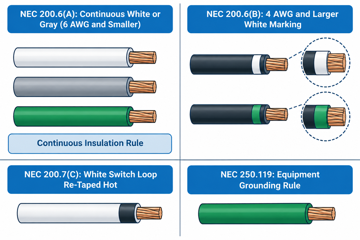
Many contractors believe the National Electrical Code mandates the phase colors be black, red, blue, brown, orange, and yellow. In reality, NFPA 70 only mandates specific colors for three conductor types. These are grounded neutrals (NEC 200.6), equipment grounding conductors (NEC 250.119), and the high-leg delta conductor (NEC 110.15). The other ungrounded phase colors are standard color trade conventions. However, NEC 210.5(C) requires each ungrounded wire to be marked by phase and system when multiple voltage systems share a building.
As indicated in OSHA Standard Interpretation 1980-02-18, connecting a grounded conductor to the wrong receptacle terminal leaves it improperly identified, and NEC Section 200-7 prohibits using white or gray conductors as ungrounded wires. Field inspectors fail a number of commercial conduit jobs due to the mix-up of the two rules. The rule for a conductor in a conduit is entirely different from the rule for cable assemblies of conductors.
First, in the case of single insulated grounded neutral and equipment grounding conductors pulled through conduit (such as THHN/THWN-2), 4 AWG is the smallest wire size allowed for field re-identification. NEC 200.6(B) and NEC 250.119(A) set this strict boundary above 6 AWG. At 4 AWG and up, an installer can mark a neutral by wrapping white or gray tape around a black wire at all terminations. They can also mark an equipment ground by wrapping green tape around the exposed length of the conductor. For 6 AWG, 8 AWG, 10 AWG, 12 AWG, and 14 AWG single wires in conduit, you must pull continuous white, gray, or green insulation. Code compliance prohibits phase-taping small single conductors in conduit. Also, NEC 200.7(A) prohibits re-taping single white, gray or green conduit wires for use as hot phase conductors of any gauge.
Second, NEC 200.7(C) provides a very narrow exception for multi-conductor cable assemblies, such as 14/2 and 12/2 NM-B Romex and MC cable. Inside a cable jacket, the white or gray wire may be re-marked with black or red tape at every visible box. This re-identified wire can then feed a switch loop or a 240V load that doesn’t require a neutral.
| Conductor Category | NEC / OSHA Clause | Mandatory Color or Marking | Field Phase-Tape Rule in Conduit (Single THHN) | Multi-Conductor Cable Exception (NM-B / MC) |
|---|---|---|---|---|
| Grounded Neutral (≤6 AWG) | NEC 200.6(A); OSHA 1910.304 | Continuous white, continuous gray, or 3 continuous white/gray stripes | Prohibited — must use continuous white or gray insulation | White wire may be re-taped as hot switch/240V leg per NEC 200.7(C) |
| Grounded Neutral (≥4 AWG) | NEC 200.6(B) | Continuous white/gray OR distinctive white/gray marking at terminations | Permitted — black conductor ≥4 AWG may be taped white or gray | Permitted at termination points |
| Equipment Ground (≤6 AWG) | NEC 250.119; OSHA 1910.304(f) | Bare copper, continuous green, or green with ≥1 yellow stripes | Prohibited — must pull continuous green or bare conductor | Integral bare or green ground wire; never re-identify as hot or neutral |
| Equipment Ground (≥4 AWG) | NEC 250.119(A) | Bare, green, green-yellow, or permanent green marking at accessible points | Permitted — insulation stripped or colored green at all accessible points | Permitted for ≥4 AWG under qualified maintenance conditions |
| High-Leg Delta Phase B | NEC 110.15 & 230.56 | Durable outer finish or tagging that is Orange in color | Mandatory at every splice and panel where a neutral is also present | Mandatory orange marking on the 208V-to-ground phase leg |
| Ungrounded Phase Legs (L1/L2/L3) | NEC 210.5(C) | Any color EXCEPT white, gray, green, or green-yellow; posted legend required | Phase tape permitted on black conductors to denote L1/L2/L3 system | Standard factory phase colors (Black, Red, Blue) |
Three-Phase Wire Color Codes: 120/208V Low Voltage vs 277/480V High Voltage Systems
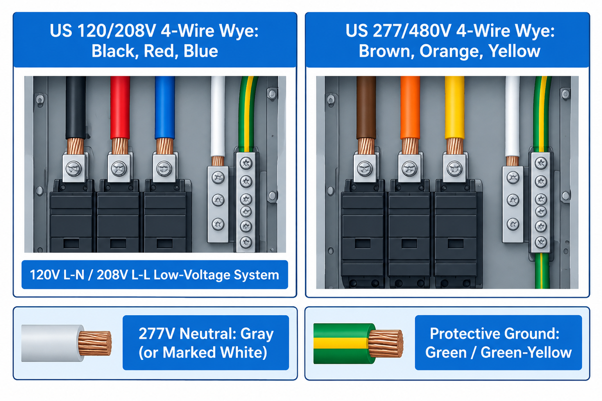
In North American commercial construction, contractors will call 120/208V panels “low-voltage” and 277/480V boards “high-voltage” systems. Per IEC 61557-1 and the NEC, all AC distribution systems at 1,000 V and below are considered low-voltage systems. That said, 277/480V systems create more than double the line-to-ground voltage of 120/208V systems. To prevent cross connections and the resultant hazards, standard wiring color codes mandate two distinct color schemes for 277/480V and 120/208V systems.
State adoption trackers like NFPA NEC enforcement maps and Washington L&I electrical rules require compliance with NEC 210.5(C) and NEC 200.6(D) when two voltage systems are in the same room. In a 120/208V 4-wire Wye system, wiring color codes for AC phases are black (Phase A), red (Phase B) and blue (Phase C). The neutral wire is white. In a 277/480V 4-wire Wye power system, Phase A is brown, Phase B is orange, and Phase C is yellow. Its neutral wire is gray. Connecting white neutrals to the 120/208V system and gray neutrals to the 277/480V system satisfies the requirements of NEC 200.6(D).
ELECTRICAL WARNING:
Electricians wiring high-mast stadium and sports LED flood lights rated 277-480V AC must pay attention to 120/240V High-Leg Delta services. On a center-tapped high-leg delta transformer, Phases A and C measure 120V to ground. Phase B, known as the ‘wild’ or ‘stinger’ leg, measures 208V to ground. NEC 110.15 requires a 208V high leg to be marked orange. In select utility areas where orange conflicts with 480V panels, purple marks the high leg so no crew connects a 120V load between Phase B and neutral.
| Three-Phase System Type | Phase A (L1) | Phase B (L2) | Phase C (L3) | Neutral (N) | Equipment Ground (PE) | Phase-to-Neutral / Phase-to-Phase Voltage |
|---|---|---|---|---|---|---|
| US 120/208V 4-Wire Wye | Black | Red | Blue | White | Green / Bare Copper | 120V L-N (all phases) / 208V L-L |
| US 277/480V 4-Wire Wye | Brown | Orange | Yellow | Gray (or marked White) | Green / Green-Yellow | 277V L-N (all phases) / 480V L-L |
| US 120/240V 4-Wire High-Leg Delta | Black (120V to N) | Orange High-Leg (208V to N) | Blue (120V to N) | White | Green / Bare Copper | 120V L1/L3-N; 208V L2-N / 240V L-L |
| Canada CEC 120/208V 4-Wire Wye | Red | Black | Blue | White | Green / Bare Copper | 120V L-N / 208V L-L (Note Red-Black L1/L2 swap) |
| Canada CEC 347/600V 4-Wire Wye | Orange | Brown | Yellow | White | Green / Bare Copper | 347V L-N / 600V L-L industrial lighting |
What Is the Color Code for 480 Volt Electrical Wires?
In US 277/480V three-phase Wye electrical installations, the phase wire colors are brown for Phase A, orange for Phase B, and yellow for Phase C. Each phase conductor measures 277V to ground and 480V phase-to-phase. The grounded neutral wire is gray (or white with a permanent system tag under NEC 200.6(D)). The equipment ground wire is green, green with a yellow stripe, or bare copper.
International IEC 60445 and European Harmonized Cable Colour Codes
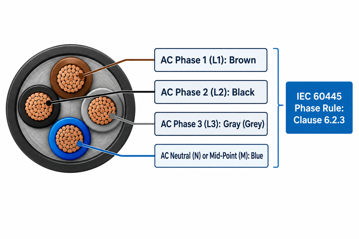
Outside North America, the International Electrotechnical Commission standard IEC 60445:2021 governs conductor colors and terminal markings. It aligns with European CENELEC document HD 308 S2 and the 2026 update IEC 60445:2021/AMD1:2026. European and Asian luminaire factories build internal wiring assemblies to these IEC AC wiring color codes. The standard also pairs every insulation color with a two-letter alphanumeric code on wiring schematics.
References from Industrial Monitor Direct and Farnell Electronics provide a preliminary guide to electrical standards in Europe. According to IEC 60445:2021 Clauses 6.2.2 and 6.2.3, in AC systems, neutral or mid-point conductor is indicated by Blue (BU) while the AC line conductor is indicated by Brown (BN), Black (BK), or Gray (GY). Project engineers verify three core rules in IEC 60445 Clauses 6.2 and 6.3 during luminaire inspection:
- On single-phase AC (230V 50Hz) circuits, Line (L) is Brown (
BN) and Neutral (N) is Blue (BU). Protective Earth (PE) uses Green-and-Yellow (GNYE) insulation. - On three-phase AC (230/400V 50Hz) feeders, Line 1 (L1) is Brown (
BN), Line 2 (L2) is Black (BK), and Line 3 (L3) is Gray (GY). Neutral (N) is Blue (BU), and Protective Earth (PE) is Green-and-Yellow (GNYE). - Under the 30%–70% bicolor earth rule (Clause 6.3.2), any 15 mm section of a green-and-yellow earth wire must have one color covering 30% to 70% of the surface. The second color covers the remainder. Solid green or solid yellow wires are not compliant protective earth conductors under IEC 60445.
| Conductor Function | IEC Terminal Symbol | Insulation Color | IEC 60445 Two-Letter Code | Relevant IEC Clause |
|---|---|---|---|---|
| AC Phase 1 (Single or 3-Phase) | L or L1 | Brown | BN |
Clause 6.2.3 |
| AC Phase 2 (3-Phase) | L2 | Black | BK |
Clause 6.2.3 |
| AC Phase 3 (3-Phase) | L3 | Gray (Grey) | GY |
Clause 6.2.3 |
| AC Neutral or DC Mid-Point | N or M | Blue | BU |
Clause 6.2.2 |
| Protective Earth Conductor | PE | Green-and-Yellow (30%–70% per 15 mm) | GNYE |
Clause 6.3.2 |
| Protective Bonding / PEN Conductor | PEN | Green-and-Yellow with Blue end markings (or Blue with GNYE end markings) | GNYE + BU |
Clause 6.3.3 |
| Functional Earthing Conductor | FE | Pink (Cream/White in legacy telecom) | PK |
Clause 6.2.5 |
What Is the IEC Standard for Cable Color Codes?
IEC 60445 is the standard published by the International Electrotechnical Commission for identifying conductors by color and alphanumeric code. For single-phase AC wiring, this standard defines brown (BN) for live, blue (BU) for neutral and green-yellow (GNYE) for protective earth. For three-phase AC distribution cables, this standard defines brown (L1), black (L2), gray (L3), blue (neutral) and green-yellow (protective earth).
UK BS 7671 Pre-2004 vs Post-2004 Wiring Colours and Regional Variations (CEC, AU/NZ, India)
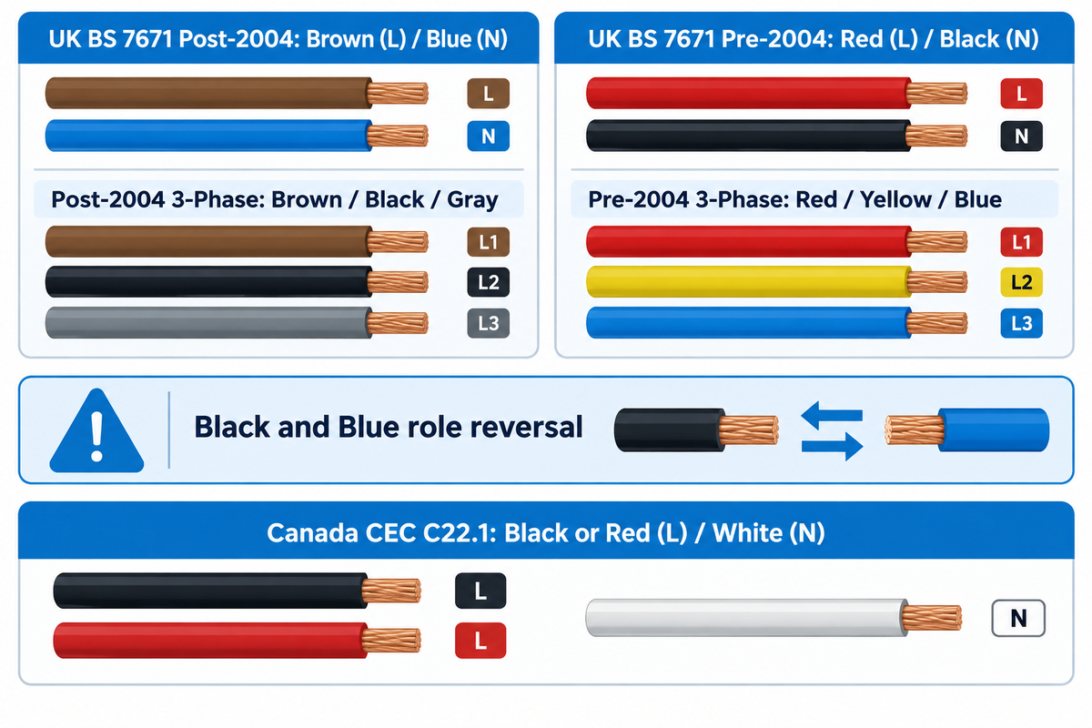
Facility engineers retrofitting lighting in older British, Commonwealth, or Asian buildings face a major wiring transition hazard. Between March 31, 2004 and March 31, 2006, the United Kingdom amended IET Wiring Regulations BS 7671. That update replaced traditional Red/Black and Red/Yellow/Blue color conventions with European CENELEC HD 308 and IEC 60445 harmonized colour codes.
Why does that transition create severe electrical hazards during luminaire upgrades? In pre-2004 UK BS 7671 wiring (and legacy Indian and Australian panels), Black was the Neutral wire and Blue was the Phase L3 live wire. Under post-2004 harmonized BS 7671 rules, those two colors swapped roles. Black became Phase L2 Live (230V/400V), and Blue became the Neutral wire. Under BS 7671 Regulation 514.14, any UK panel containing both old and new wiring colour schemes must display a yellow caution notice.
In India, the Bureau of Indian Standards issued IS 11353:2023 to align with IEC 60445:2021 coding standards. However, most existing Indian commercial buildings still run on the legacy Red (R), Yellow (Y), and Blue (B) phase sequence with a Black neutral. Australia and New Zealand (AS/NZS 3000) maintain Red, White, and Blue for three-phase active conductors, alongside Black or Light Blue for neutral. When municipal LED street light manufacturers supply pre-wired luminaires for export, pole-base terminal blocks are stamped L1/L2/L3/N/PE. This clear labeling lets local crews terminate different electrical wire colors without confusion.
| Region & Standard | Single-Phase Live / Neutral | 3-Phase L1 / L2 / L3 | 3-Phase Neutral (N) | Protective Earth (PE) |
|---|---|---|---|---|
| UK BS 7671 (Post-March 2004 Harmonized) | Brown (L) / Blue (N) | Brown / Black / Gray | Blue | Green-Yellow (sleeved at terminations) |
| UK BS 7671 (Pre-March 2004 Legacy) | Red (L) / Black (N) | Red / Yellow / Blue | Black | Green-Yellow (or solid Green pre-1977) |
| Canada (Canadian Electric Code C22.1) | Black or Red (L) / White (N) | Red (L1) / Black (L2) / Blue (L3) | White | Green or Bare Copper |
| Australia & New Zealand (AS/NZS 3000) | Brown or Red (Active) / Blue or Black (N) | Red / White / Blue (or Brown/Black/Gray) | Black or Light Blue | Green-Yellow Stripe |
| India (LegacyCEA / IS 732 vs IS 11353:2023) | Red (L) / Black (N) [IEC: Brown/Blue] | Red (R) / Yellow (Y) / Blue (B) | Black (or Blue in new IEC panels) | Green or Green-Yellow |
DC Power, Solar Photovoltaic, and 12V/24V LED Driver Wire Color Codes
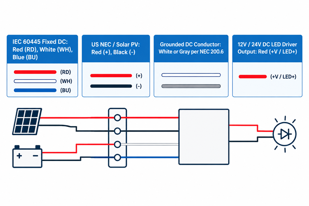
Direct current (DC) wiring systems power solar arrays, battery storage cabinets, telecom racks, and 12V/24V LED luminaires. Unlike AC power, DC circuits maintain constant polarity. Reversing positive and negative leads on a DC electrical load immediately destroys LED chips, capacitors, or charge controllers. Also, under OSHA 1910.304 and NEC Article 690, solar PV and battery strings remain energized when the main AC breaker is open.
Modern international standards recently updated DC conductor colors under IEC 60445:2021 Clause 6.2.4. In legacy US automotive, marine, and low-voltage electronics assemblies, Red is positive (+) and Black is negative (-). However, hybrid AC/DC buildings present a cross-wiring risk if electricians confuse a black DC negative wire with a black AC phase wire. To prevent this, IEC 60445:2021 specifies Red (RD) for DC positive (+), White (WH) for DC negative (-), and Blue (BU) for the DC mid-wire (M).
Outdoor lighting projects frequently install commercial solar LED flood lights or compare solar flood lights versus AC wired floodlight installations. On these job sites, IP67 waterproof DC connectors often bridge two different cord conventions. The solar panel or LiFePO4 battery lead assembly typically uses Red (+) and Black (-). Meanwhile, European 24V DC LED drivers output Brown (+V) and Blue (-V) on their secondary leads. Always check the molded + and - arrows on M12 or M16 plugs to ensure proper wire polarity.
| DC System Application | Positive (+) Ungrounded | Negative (-) Ungrounded | Grounded Conductor / Mid-Wire (M) | Equipment Ground (PE) |
|---|---|---|---|---|
| IEC 60445:2021 Fixed DC Power (Clause 6.2.4) | Red (RD) |
White (WH) |
Blue (BU) Mid-Wire |
Green-Yellow (GNYE) |
| US NEC Ungrounded 2-Wire DC / Solar PV | Red (or Black with Red sleeve) | Black | White or Gray (if system is grounded per NEC 200.6) | Green or Bare Copper |
| 12V / 24V DC LED Driver Output (North America) | Red (+V / LED+) |
Black (-V / LED-) |
N/A (Class 2 isolated output) | Chassis Green (on primary side) |
| 12V / 24V DC LED Luminaire Tail (IEC / EU) | Brown (+V) |
Blue (-V) |
N/A | Green-Yellow (if Class I housing) |
Commercial Lighting, 0-10V Dimming (Purple, Pink, Gray), and 5-Wire Cable Color Codes
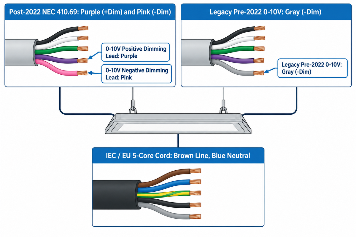
In commercial electrical work, a 5-wire electrical cable serves two distinct roles. It can carry three-phase AC power (L1/L2/L3/N/PE) or single-phase luminaire power with a 0-10V dimming loop (L/N/PE/DIM+/DIM-). Confusing these two 5-wire cables, or miswiring the gray lead in a 277V ceiling grid, is the leading cause of burned-out commercial LED drivers in North America.
Here’s why we enforce the 277V Gray-Neutral vs 0-10V Dimming Separation Rule on every lighting project. Before 2022, LED driver makers used Purple (Violet) for 0-10V positive (+Dim) and Gray for 0-10V negative (-Dim). At the same time, US 277/480V lighting panels use Gray for the 277V AC grounded neutral wire. In dark ceiling plenums, electricians routinely spliced the fixture’s gray 0-10V dimming lead into the 277V gray power neutral bundle. That mistake sent 277V AC current into the Class 2 dimming circuit and destroyed every driver on the dimmer zone.
Industry reports from Electrical Contractor Magazine, Inside Lighting, and the Municipality of Princeton contract documents provide the details about the regulations. NFPA 70 added NEC Article 410.69 (effective January 1, 2022), which prohibits gray insulation on field-connected luminaire control conductors unless permanently re-identified at all visible and accessible points. NEMA then standardized Purple (+Dim) and Pink (-Dim) as the common color pair for 0-10V dimming leads. Because 0-10V drivers source a low DC current across Purple and Pink, an open dimming wire causes the fixture to fail safe to 100% full brightness. Shorting Purple and Pink together dims the fixture to minimum output. For multi-channel DMX512 or DALI-2 fixtures, consult our LED lighting controller and DMX512/0-10V wiring guide.
| 5-Wire Cable / Installation Scenario | Wire 1 | Wire 2 | Wire 3 | Wire 4 | Wire 5 | Critical Field Verification Action |
|---|---|---|---|---|---|---|
| 1. Commercial 0-10V Dimming Cord (Post-2022 NEC 410.69) | Black (120/277V Line) | White (Neutral) | Green (Ground) | Purple (0-10V +Dim) | Pink (0-10V -Dim) | Keep Purple/Pink isolated from 120V/277V mains unless using Class 1 rated MC-PCS cable. |
| 2. Legacy 0-10V Dimming Cord (Pre-2022 Stock) | Black (120/277V Line) | White (Neutral) | Green (Ground) | Purple (0-10V +Dim) | Gray (0-10V -Dim) | Wrap pink tape on the gray dimming lead immediately; never splice to 277V gray power neutral. |
| 3. IEC / EU 0-10V or DALI-2 5-Core Luminaire Cord | Brown (230V Line) | Blue (Neutral) | Green-Yellow (PE) | Purple or Black (DA+ / Dim+) | Pink or Gray (DA- / Dim-) | DALI-2 control pairs (DA+/DA-) are polarity-insensitive; 0-10V pairs are polarity-sensitive. |
| 4. IEC 60445 5-Core Three-Phase Power Cable | Brown (L1) | Black (L2) | Gray (L3) | Blue (Neutral) | Green-Yellow (PE) | Verify phase rotation (L1-L2-L3) before energizing three-phase motors or HVAC skids. |
| 5. US SOOW 5-Conductor Portable 3-Phase Cord | Black (Phase A) | Red (Phase B) | Blue (Phase C) | White (Neutral) | Green (Ground) | In some 5-wire industrial SOOW cords, Orange replaces Blue or Red; check printed legend. |
| 6. UK Pre-2004 Retrofit to Harmonized 5-Core | Red → Brown (L1) | Yellow → Black (L2) | Blue → Gray (L3) | Black → Blue (Neutral) | GNYE → GNYE (Earth) | Affix BS 7671 Regulation 514.14 dual-color caution label on the distribution board cover. |
What Is the Color Code for a 5-Wire Cable?
A 5-wire cable uses brown, black, gray, blue, and green-yellow for IEC three-phase power, or black, white, green, purple, and pink for US 0-10V dimming luminaires. In US portable three-phase SOOW cords, the five conductors are black (Phase A), red (Phase B), blue (Phase C), white (neutral), and green (ground). In pre-2022 commercial dimming fixtures, the fifth control wire was gray.
Industrial Control Panels (NFPA 79 / UL 508A), Multi-Conductor Charts, and NM-B Jacket Colors
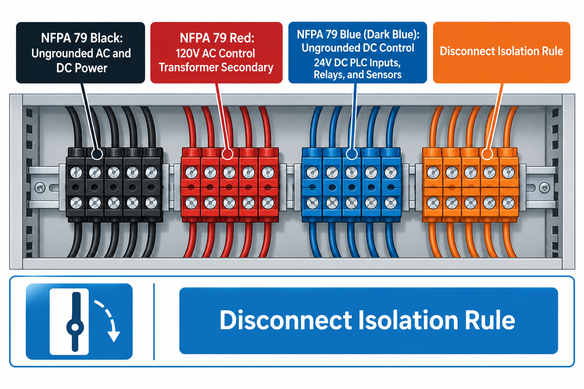
Industrial machinery cabinets and residential wiring follow two additional identification standards. Control panel interiors follow NFPA 79 (Electrical Standard for Industrial Machinery) and UL 508A. Residential cables in North America use NEMA color coded outer PVC jackets on NM-B (Romex) cable.
In an industrial control cabinet, wire color indicates the circuit’s voltage class and lockout status rather than the voltage class and phase sequence used for three-phase building wiring. Under NFPA 79 Clause 13.2, Black marks all ungrounded AC and DC power conductors, such as 480V motor leads. AC control circuits (typically 120V AC) are marked in red, and DC control circuits (24V DC PLC I/O) are marked in blue. Most importantly, control wires that are fed by an external source and are interlocked are marked in orange. These conductors remain ‘live’ even when the main disconnect switch of the cabinet is locked in the OFF position.
| Internal Panel Wire Color | NFPA 79 Clause 13.2 Circuit Function | Typical Voltage in Panel | Lockout / Tagout Safety Implication |
|---|---|---|---|
| Black | Ungrounded AC and DC power conductors | 208V / 480V AC motor & heater power | De-energized when main cabinet disconnect is open. |
| Red | Ungrounded AC control circuit conductors | 120V AC control transformer secondary | De-energized when main disconnect opens (unless externally fed). |
| Blue (Dark Blue) | Ungrounded DC control circuit conductors | 24V DC PLC inputs, relays, and sensors | Verify 24V power supply isolation before pulling terminal blocks. |
| Orange | Excepted / Interlocked circuits fed from external source | 24V DC or 120V AC remote interlock | LIVE WHEN MAIN DISCONNECT IS OFF — requires separate upstream lockout. |
| White (or Gray / White with Blue Stripe) | Grounded AC control neutral (White) / Grounded DC common (White w/ Blue stripe) | 0V reference to panel ground bus | Never open grounded control common without isolating control supply. |
| Green (with or without Yellow Stripe) | Equipment grounding / protective bonding conductor | 0V chassis bond | Must bond cabinet door, backplane, and incoming conduit. |
In North American wood-frame construction, NEMA standardizes the OUTER JACKET COLOR of nonmetallic-sheathed cable (NM-B) by American Wire Gauge (AWG). Based on NEC Table 310.16 ampacity guidelines and NEC 334.80, NM-B cable is limited to the 60°C AMPACITY COLUMN. Individual THHN/THWN-2 wires in conduit terminate on 75°C COMMERCIAL BREAKERS (CalcEngineer NEC 310.16 derating guide).
Consider branch-circuit voltage-drop calculations for an outdoor lighting feeder carrying a 16 A continuous load over a 150 ft one-way run. Using NEC Chapter 9, Table 8 uncoated copper DC resistance values (V drop = 2 × L × I × R / 1000), the three gauges compare as follows:
- Using 14 AWG (White NM-B Sheath, 15 A max breaker, R = 3.07 Ω/1000 ft) is prohibited on a 16 A load because it violates the 15 A breaker limit. It would drop 2 × 150 × 16 × 3.07 / 1000 = 14.74 V (12.3% drop on 120V).
- Pulling 12 AWG (Yellow NM-B Sheath, 20 A breaker, R = 1.93 Ω/1000 ft) satisfies the 20 A breaker rule (16 A is 80% of 20 A). However, it drops 2 × 150 × 16 × 1.93 / 1000 = 9.26 V (7.7% drop at 120V, exceeding the 3% target).
- Upgrading to 10 AWG (Orange NM-B Sheath, 30 A breaker, R = 1.21 Ω/1000 ft) drops 2 × 150 × 16 × 1.21 / 1000 = 5.81 V. That equals 4.8% at 120V, which still exceeds the 3% target, and 2.42% at 240V, which passes the <3% voltage-drop limit for LED drivers.
B2B Luminaire & Pre-Wired Cable Assembly Procurement Checklist (UL 1598 vs. EN 60598)
When ordering pre-wired outdoor floodlights, street lights, and 24V DC architectural palm tree ring lights for international projects, specify the five items below on your purchase order:
- Item 1 — Target Market Core Color Standard: North American shipments use UL 1598 / NEC (
Black / White / Green), while European, UK, Middle Eastern, and Australian shipments use EN 60598 / IEC 60445 (Brown / Blue / Green-Yellow). - Item 2 — Outer Cord Jacket Rating & Gauge: North American luminaires use UL SJTW or SOOW 18/3 or 16/3 (300V/600V), whereas IEC outdoor jobs use HAR H05RN-F or H07RN-F 3G1.0mm² or 3G1.5mm² rubber cord.
- Item 3 — Dimming & Control Lead Compliance: Factory 0-10V dimming leads use Purple (+Dim) and Pink (-Dim) per NEC 410.69 and municipal rules like City of Berkeley Technical Specifications, while DALI-2 drivers use
DA+/DA-leads. - Item 4 — Heat-Shrink Ferrule Terminal Tags: UL 969 heat-shrink markers printed with
L,N,PE,DIM+, andDIM-via dual-sleeve identification methods (US Patent US12671235B2 and US Patent US6311637B1) keep terminal tags legible after UV and heat exposure. - Item 5: Waterproof IP67/IP68 Connector Pinout Sheet: Modular DC and DMX luminaire submittals include a factory pin-to-color diagram mapping Pin 1, Pin 2, Pin 3, and Pin 4 to their exact conductor colors.
How to Identify Unlabeled or Faded Wires Safely: 3-Step Multimeter Verification Protocol
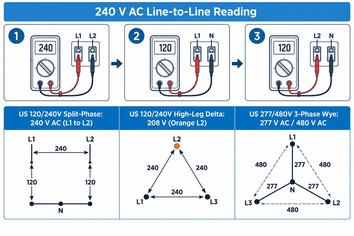
Wire identification is complicated by insulation that fades at high temperatures, paint applied during renovations, or improper switch-loop splices. As stated in the OSHA Electrical Training Materials, reliance on wire color alone without meter verification leads to severe reversed polarity shock.
Prior to any voltage testing, OSHA 29 CFR 1910.334(c) and 29 CFR 1910.333(b)(2) enforce the following safety rules. A live test must be conducted by a qualified person wearing arc flash PPE and using a CAT III 600V or CAT IV 1000V True RMS Multimeter. Always test the meter on a known live source before and after probing (“Prove-Test-Prove”). Lastly, opening a single branch-circuit breaker may leave other sources of power energized by multiwire neutrals, battery inverters, solar backfeeds or NFPA 79 orange interlock circuits. Every upstream disconnect must be isolated prior to working on bare conductors.
Qualified electricians use our 3-Step Multimeter Conductor Verification Protocol to identify unknown or faded wire(s) prior to landing on a luminaire:
- In Step 1, perform a De-Energized Ground Continuity Check (Power OFF & Locked Out). Isolate all power sources, lock out the breaker, and verify 0.0 V across all wires. Set the multimeter to resistance (Ω) and measure each wire against the grounded metal box. The Equipment Ground (PE) reads near 0.0 to 0.5 Ω continuously. The Neutral bus shows low resistance to ground, while ungrounded phase legs with open loads read Open Loop (
OL). - In Step 2, perform an Energized Line-to-Ground & Neutral-to-Ground Voltage Check (Controlled Power ON). Separate all conductors in insulated test connectors and restore circuit power. Set the CAT III/IV meter to AC Volts (V~) and touch the black probe to the verified Equipment Ground (PE).
- An Ungrounded Hot / Phase (L) wire reads full line-to-ground voltage (120V on US split-phase/208V Wye, 208V on High-Leg Delta Phase B, 230V on IEC 60445, or 277V on US 480V Wye).
- A Grounded Neutral (N) wire reads 0 V nominal (typically under 2 V due to normal load return current). Confirm Neutral by measuring Phase-to-Neutral, which reads a steady 120V, 230V, or 277V.
- In Step 3, perform a Phase-to-Phase Voltage & Rotation Check (3-Phase Circuits). Measure voltage between each pair of phase wires (
L1-L2,L2-L3,L1-L3) to confirm balanced three-phase voltage (208V, 400V, or 480V). Use a phase rotation meter to account for proper phase rotation (clockwiseA-B-C), then tag each wire with UL 969 markers.
| Electrical System | Phase to Ground (L–PE) | Phase to Neutral (L–N) | Phase to Phase (L1–L2 / L2–L3) | Neutral to Ground (N–PE) |
|---|---|---|---|---|
| US 120/240V Split-Phase | 120 V AC | 120 V AC | 240 V AC (L1 to L2) | 0 V (<2 V nominal) |
| US 120/208V 3-Phase Wye | 120 V AC | 120 V AC | 208 V AC | 0 V (<2 V nominal) |
| US 120/240V High-Leg Delta | 120 V (L1/L3); 208 V (Orange L2) | 120 V (L1/L3); 208 V (Orange L2) | 240 V AC (all phase pairs) | 0 V (<2 V nominal) |
| US 277/480V 3-Phase Wye | 277 V AC | 277 V AC | 480 V AC | 0 V (<2 V nominal) |
| IEC / UK / EU 230/400V 3-Phase | 230 V AC | 230 V AC | 400 V AC | 0 V (<2 V nominal) |
Frequently Asked Questions
1. What are the OSHA standards for electrical wire color coding?
OSHA 29 CFR 1910.304(a)(2) and 1910.304(f) require white or gray for grounded neutrals and bare, green, or green-yellow for equipment grounds.
Regarding workplace rules, OSHA aligns with NFPA 70 across all commercial and industrial facilities. OSHA doesn’t mandate the use of specific colors for ungrounded hot phases, as long as they don’t use white, gray, green or green-yellow insulation. It’s the responsibility of the Facility Operator to post a permanent color legend at each panel if different voltage systems exist in the same building.
2. Can you use a white wire as a hot wire under NEC rules?
Yes, under NEC Article 200.7(C), a white or gray wire inside a multi-conductor cable may serve as a hot wire if permanently re-marked.
This cable exception applies to sheathed cables such as 14/2 or 12/2 NM-B Romex or MC cable feeding switch loops or 240V loads without a neutral. The installer must wrap black, red, or other non-green phase tape around the white wire at every visible box. Single white wires pulled through conduit can’t be re-marked as hot phase conductors.
3. How do you connect a European or UK light fixture (brown and blue wires) to US wiring (black and white)?
Connect the European brown (BN) live wire to the US black hot wire, blue (BU) to US white neutral, and green-yellow (GNYE) to ground.
Before energizing the circuit, check the luminaire’s internal LED driver label to confirm it accepts North American 120V or 277V 60Hz power. Many commercial export LED drivers feature universal 100–277V AC 50/60Hz input and work smoothly on US branch circuits. However, 230V-only European drivers will under-perform on 120V or fail on a 277V lighting circuit. Always use UL-listed lever connectors or wire nuts rated for stranded metric copper when joining European cords to solid AWG building wire.
4. What is the color code for a 3-wire AC cable in the US vs UK?
US 3-wire AC cables use Black (Hot), White (Neutral), and Green (Ground), whereas UK and IEC cables use Brown (Live), Blue (Neutral), and Green-Yellow (Earth).
In older UK buildings (pre-2004) 3-core cables use Red for live, Black for neutral and Green-Yellow for protective earth.
5. Why did commercial 0-10V dimming wire colors change from purple and gray to purple and pink?
NEC Article 410.69 replaced the gray 0-10V dimming negative wire with pink on January 1, 2022 to prevent cross-wiring with 277V gray power neutrals.
Before 2022, commercial 0-10V LED drivers used purple (+Dim) and gray (-Dim). Because US 277/480V panels also use gray for the 277V grounded neutral wire, installers frequently spliced the gray dimming lead into the 277V neutral bundle. That error sent 277V AC into the low-voltage dimming bus and destroyed the drivers. Using purple (+Dim) and pink (-Dim) eliminates that mistake.
6. What do the outer jacket colors on Romex (NM-B) building cable indicate?
North American NM-B (Romex) outer jacket colors indicate wire gauge: White is 14 AWG (15A), Yellow is 12 AWG (20A), Orange is 10 AWG (30A), and Black is 8 or 6 AWG.
Check the nylon sheath of the cable before landing on a breaker and make sure it states the AWG size.
7. Is it safe to identify an electrical wire solely by its insulation color?
No, you must never trust insulation color alone before touching or splicing an electrical conductor.
Previous renovations, unmarked white switch loops or a mixture of pre-2004 UK and IEC cables can result in live, white, blue and black wires at full line voltage. Perform a Three-Step Multimeter Verification test with a CAT III/IV meter prior to working on bare copper.
References & Sources
- U.S. Occupational Safety and Health Administration (OSHA) – [29 CFR 1910.304: Wiring Design and Protection] (Grounded neutral and equipment grounding conductor identification).
- U.S. Occupational Safety and Health Administration (OSHA) – [Standard Interpretation 1997-12-18-0: Electrical Conductor Identification].
- U.S. Occupational Safety and Health Administration (OSHA) – [Standard Interpretation 1980-02-18: Citing of Reversed Polarity and NEC Section 200-7].
- U.S. Occupational Safety and Health Administration (OSHA) – [OSHA Electrical Safety Training Library (Reversed Polarity Hazards)].
- National Fire Protection Association (NFPA) – [Understanding NFPA 70, National Electrical Code (NEC) Articles 200.6, 200.7, 210.5, 250.119, and 410.69].
- National Fire Protection Association (NFPA) NFPA 70 (NEC) State Adoption and Enforcement Maps.
- Washington State Department of Labor & Industries (L&I) Electrical Laws, Rules & Policies (NFPA 70 Adoption Schedule).
- International Electrotechnical Commission (IEC) IEC 60445:2021 Basic and Safety Principles for Man-Machine Interface, Marking and Identification of Conductors.
- Electrical Contractor & Lighting Magazine (EC&LM) Lighting Color-Coding Changes: NEC 2020 Article 410.69 Impacts 0–10V Control Wiring.
- Inside Lighting No More Gray: Low Voltage 0-10V Wiring Changes to Pink/Purple.
- Municipality of Princeton, NJ Municipal Electrical and 0-10V Lighting Control Wiring Specifications.
- City of Berkeley, CA Technical Specifications: Commercial LED Driver and Wire Color Code Requirements.
- Google Patents / USPTO US Patent US12671235B2: Conductor Identification Sleeve System & US Patent US6311637B1: Electrical Wire Identification Markers.
Trending now