Get in Touch with GUANGQI



Updated October 2026
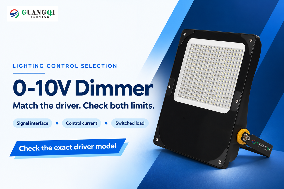
An adjustable 0-10 volt dimmer alters a compatible LED driver’s output through a separate low-voltage control signal. Choose it by the driver’s interface, current requirement, and switching load. The lowest slider position may leave the lights on: minimum brightness, electronic off and disconnecting power are different functions.
Replacing a wall control is easy once the equipment matches. A dimmable LED fixture might need a phase-cut control, a sinking analog control or a supported digital interface. Start with the driver model, and then use the checks below to guide your purchase decision.
Before buying
Match the signal interface first. Then check the milliamp budget and the actual switching device’s load, inrush and approved driver-count limits.
What is 0-10V dimming, and does it turn lights off?
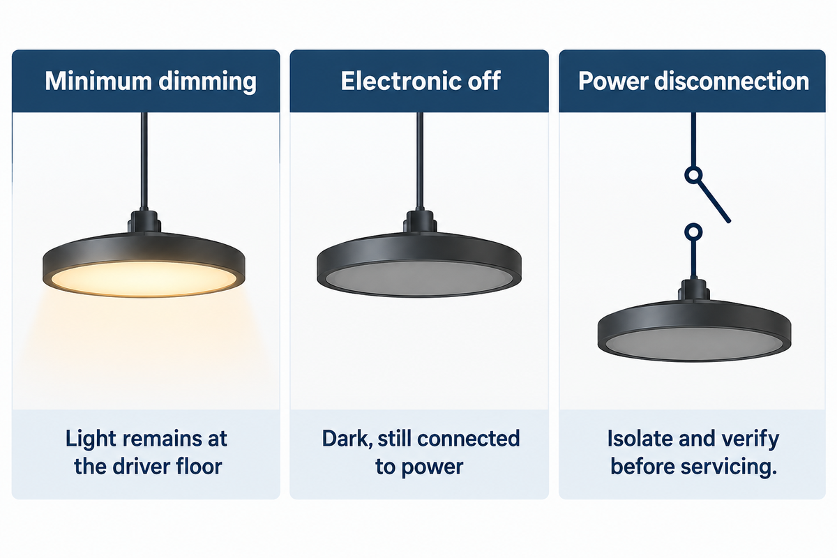
0-10V dimming sends a brightness instruction separately from the power supply, but the lowest setting may leave the lights on. A 0-10V LED driver takes operating power through its supply conductors and responds to a separate DC voltage on its dimming input. This electronic lighting control signaling adjusts LED light output; the signal doesn’t supply the energy that lights the LEDs.
The public scope of ANSI C137.1-2022 covers dimming for LED and fluorescent equipment through the driver or ballast control interface, from minimum/off to maximum output. That wording includes different low-end behaviors. A lamp remaining lit at the bottom of a 0-10V slide dimmer can be normal for its driver.
| Function | What happens | Selection consequence |
|---|---|---|
| Minimum dimming | Light output reaches the driver’s programmed floor. | Use a separate supported switching function for darkness. |
| Electronic off | A compatible signal commands zero light output; the driver remains connected to power. | Both devices must support the required off threshold. |
| Power disconnection | The appropriate switching or isolation device interrupts the supply. | Servicing still requires proper isolation and verification. |
Lutron’s Application Note 587, and Hatch, describe dim-to-off as a standby condition. Neither is permission to handle wiring; have a qualified electrician isolate and verify the circuit before work.
Nor does a 5-volt command guarantee half the light or half the input power. In a study of 23 LED street lights conducted by the Pacific Northwest National Laboratory (PNNL), the response curves were quite different. These street lights were made prior to the 2022 standard and showed varying response curves to dimming control in the tested group.
Compare 0-10V, 1-10V and phase-cut dimmers
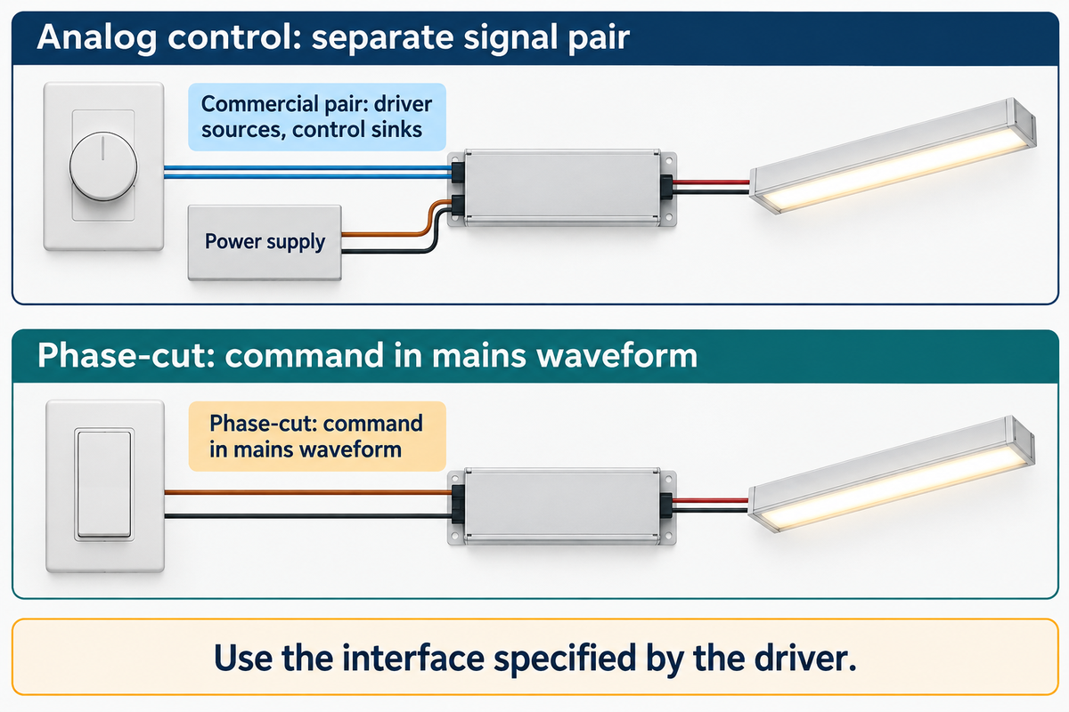
A separate analog pair distinguishes 0-10V dimming from ordinary phase-cut control. Compatible fluorescent ballasts also use this arrangement. For phase-cut control devices, the command is encoded in the mains waveform. Lutron describes the commercial arrangement as varying light output between 1 V and 10 V; at 1 V or less, the driver reaches its minimum. It’s sometimes called 1-10V because that’s the active dimming range. Select the lighting control protocol specified by the driver, not by the wallplate’s appearance.
In commercial lighting, a current-sourcing driver is paired with a current-sinking dimming control. In entertainment lighting, a 0-10 V interface with a different current-direction convention is used. ANSI E1.3’s public catalogue description identifies the entertainment control. Lutron’s application note describes the source/sink differentiation. A compatible driver-control pair is required, with matching voltage and current-direction conventions.
Can I use a regular dimmer on 0-10V?
An ordinary phase-cut LED dimmer switch can’t provide the separate control signal used by a 0-10V driver. Use the driver’s control, or a documented interface combination that converts the command. Putting a phase-cut device on the supply of a driver meant for analog dimming can be problematic.
Minimum brightness follows the driver’s dimming curve, regardless of what’s marked on the control label, be it 0-10V or 1-10V. Dimming LED fixtures fully off through the signal requires the supported electronic-off function; commanding 0 volts alone does not guarantee it. For an existing building without a control cable, the cost of adding a pair versus using a supported wireless receiver or a truly phase-cut-compatible driver should be evaluated.
Match the LED driver and control interface
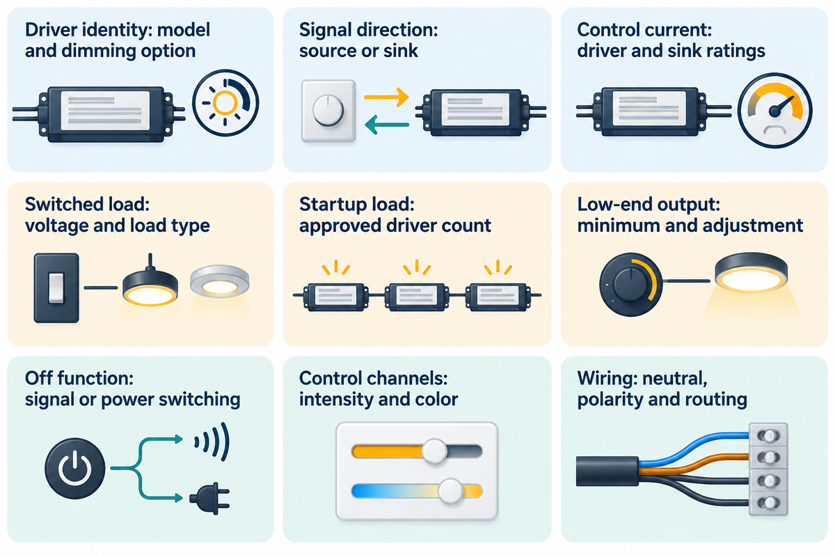
In terms of drivers and control, the model codes form the basis of comparison. Evaluate which device sources current, which sinks it and what each channel controls. Matching the electrical interface provides choices for integrating light level and off behavior in zoning and shaping the response curve for a particular room or outdoor condition.
For background regarding the power-conversion side, refer to our LED driver Guide . Use the table below when comparing a 0-10V LED dimmer switch with equipment being considered.
| Check | Record before ordering | Decision it changes |
|---|---|---|
| Driver identity | Full model and dimming option | Whether the existing driver can stay |
| Signal direction | Source, sink or documented automatic mode | Which controller can operate the input |
| Control current | Driver source current in mA and control sink rating | Maximum control-loop loading |
| Switched load | Supply voltage, load type and switch rating | Wall control versus separate relay/interface |
| Startup load | Inrush compatibility or approved driver-count table | Whether steady-state arithmetic is sufficient |
| Low-end output | Driver minimum and adjustment range | Suitability for low-light tasks |
| Off function | Electronic-off support or separate power switching | How the zone becomes dark |
| Control channels | Intensity, color or linked dim-to-warm function | Number and purpose of controls |
| Wiring arrangement | Neutral, polarity, cable and control-location requirements | Installation scope and model choice |
Source basis: Lutron and ETC application guidance, the relevant product instructions, and the U.S. Department of Energy’s explanation of color-tunable controls. DOE distinguishes linked dim-to-warm operation from tunable-white systems with separate intensity and color controls.
Features such as a light almond finish, a dimmer knob or a paddle switch don’t identify the control interface inside the wallbox. The same applies to a smart dimmer, smart LED product or home automation label: choose the supported load interface before choosing the user interface.
Plan the power and control wiring
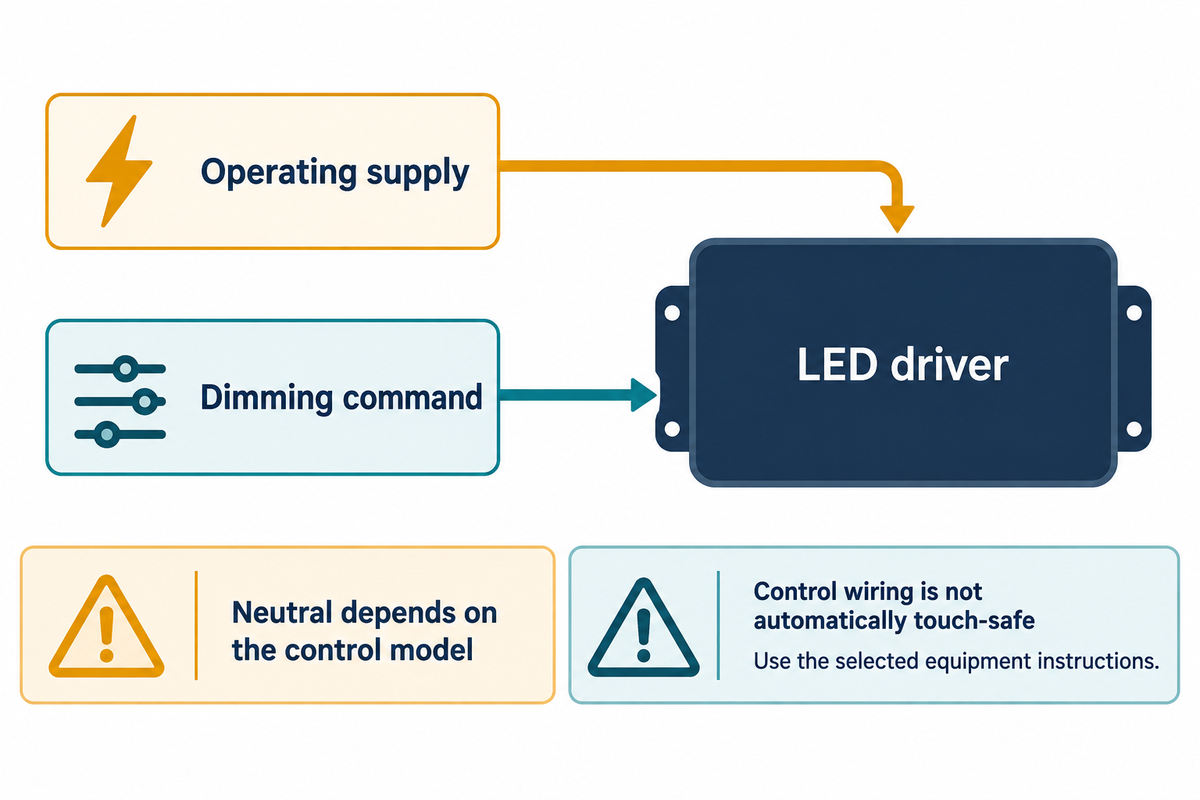
For 0-10V wiring, there are two possible paths. For 0-10V wiring, plan two paths: the driver’s operating supply and the low-voltage wiring that carries the dimming command. Connections and routing depend on the equipment, as shown in its wiring diagram. A single-pole or 3-way wall-control arrangement adds yet another choice; the presence of a control pair doesn’t tell you whether that wallbox requires a neutral.
According to Lutron’s documented commercial practice, purple identifies positive control wiring and pink identifies negative control wiring. In older installations, gray may be used for the negative lead. Refer to terminal markings and the chosen equipment. Do not identify a conductor’s function from color alone, especially when adapting existing wiring.
According to ETC, control conductors aren’t always isolated from dangerous voltages. The phrase “low voltage dimmer” doesn’t grant Class 2 wiring approval. Separation, insulation and routing are determined by the type of equipment and its installation. These details should be worked out by a licensed installer.
IP710 instructions from Leviton permit some single pole and 3-way arrangements and require only one dimmer in a circuit. In circuits controlled from multiple locations, a second ordinary dimmer isn’t allowed in place of the other switch. Larger zones may use a different type of control device called a lighting control panel to provide the necessary switching and control functions.
Size the dimmer using both control and switching limits
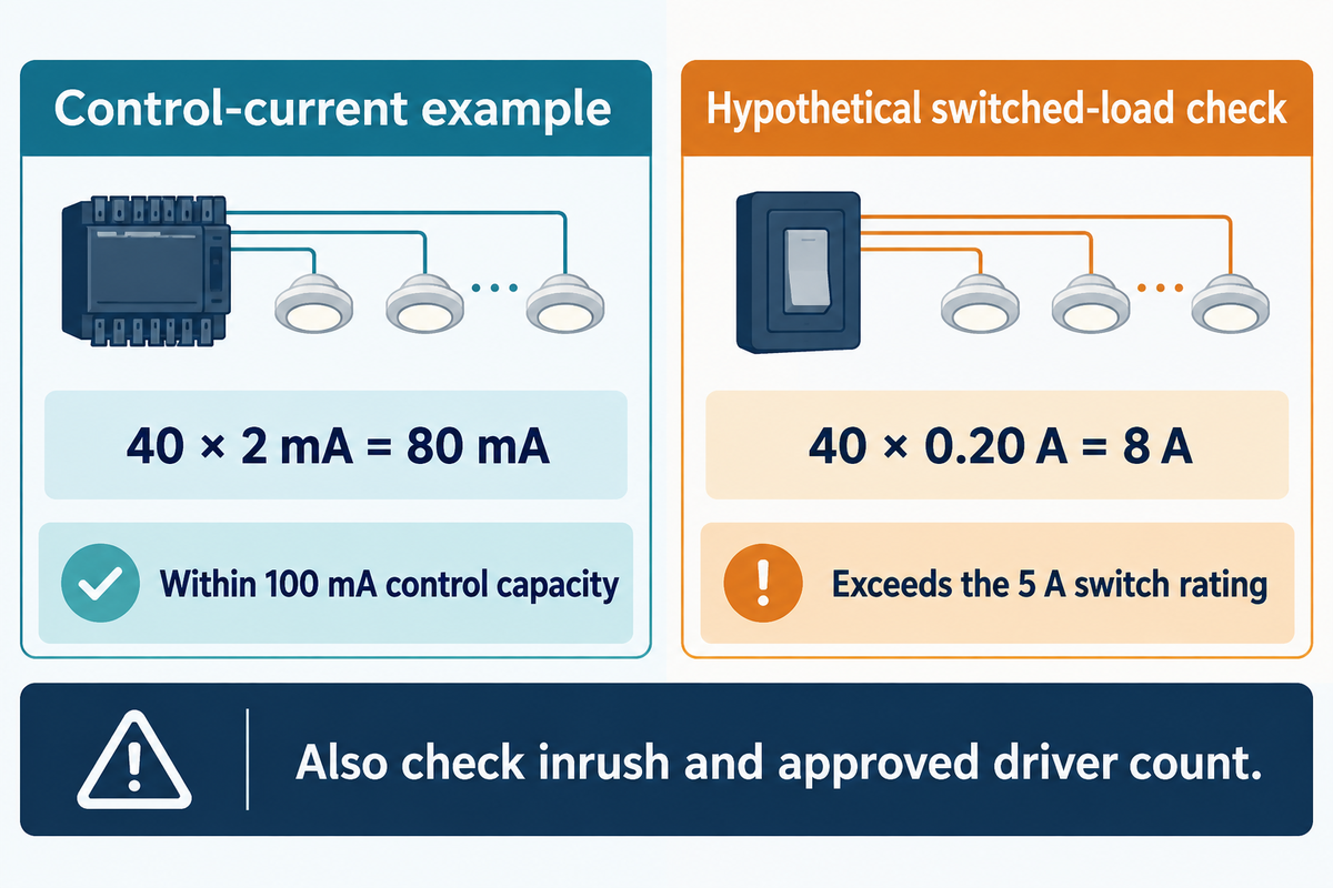
ETC’s example of a 100 mA sinking control and 2 mA per driver gives 50 drivers on the control-current budget. This example isn’t a permission to install 50 fixtures. The actual switch must handle the load (including voltage and inrush current), with the driver count within the switch manufacturer’s limit.
How many lights can you put on a 0-10V dimmer?
ETC’s example gives 50 drivers on the control-current budget (100 mA ÷ 2 mA per driver); count drivers and compare their combined control current with the dimmer’s sink capacity. In a circuit with multiple drivers, the switching device must handle the connected loads, with the driver count within the switch manufacturer’s limit. A fixture with multiple drivers can count more than once on the signal side. Mixed driver models require adding their individual specified currents rather than assuming one model’s current applies to all driver models.
2-Limit Dimmer Sizing Test
Use a budget to account for signal loading and one for power switching. Power switching has separate checks for steady state and startup loading. The first can be calculated by using the current rating; the second requires the information provided by the manufacturer (i.e. driver or load count).
ETC’s control-side example: If a sinking control has a capacity of 100 mA, and each driver sources 2 mA of control current, there would be capacity for 50 drivers in the group. A proposed group of 40 such drivers would require 80 mA, leaving 20 mA of control capacity. The 2 mA value belongs to this example; obtain the actual driver’s specified source current for a real project.
Now assume those same 40 drivers each draw 0.20 A of operating current, while the separate switching device is rated for 5 A of that load type at the project’s supply voltage. Signal demand passes at 40 × 2 mA = 80 mA. Operating demand fails at 40 × 0.20 A = 8 A, exceeding the 5 A switch rating. A higher-rated switching arrangement or smaller switched groups are needed; inrush compatibility remains another check.
| Manufacturer/model | Control sink capacity | Published power-load rating |
|---|---|---|
| Lutron DVSTV | 50 mA | 8 A, 120–277 V |
| Lutron DVSTV-453 | 50 mA | 450 W, 120–277 V |
| Leviton IP710-DL/IP710-D | 28 mA maximum | 1200 VA at 120 VAC; 1500 VA at 277 VAC |
Source: Lutron Application Note 587 Rev J and Leviton instruction sheet DI-000-IP710-02H. An 8 amp rating isn’t the same as a 450 W rating, and watts aren’t automatically equivalent to volt-Amperes.
Compatibility Testing of Switching Devices and Electronic Drivers is described in NEMA JSC 10410-2023. Further, look at ratings labels. The University of Maryland’s room controller specification lists a 250 mA, 24 V auxiliary output, which is distinct from the analog dimming output. That number isn’t the sink current allowance.
Troubleshoot flicker, uneven dimming and lights that stay on
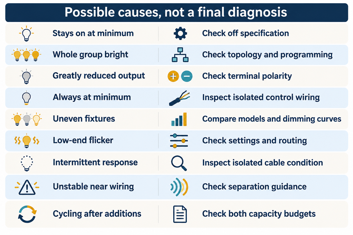
Symptom and affected group first. Compare driver and controller documentation next. One installation can have several reasons for e.g. lights staying on, or dimming issues. Don’t replace the wall control unless you’ve checked the interface, low-end settings and wiring. It can leave the original fault in place.
In one Mike Holt forum account, two groups switched normally but would not dim. The installer reported crossed control wiring and incorrectly programmed receivers. It’s a good example of why installers check more than one cause; it isn’t a failure rate study or a Guangqi service case.
| Observed pattern | Possible cause to distinguish | Next check for the installer |
|---|---|---|
| Lights stay on at minimum | Driver dimming floor; no electronic off | Off specification and power-switch function |
| Whole group stays bright | Interrupted control path or wrong configuration | Control topology and receiver programming |
| Output greatly reduced | Reversed control polarity | Terminal identification in the wiring drawings |
| Minimum output regardless of slider | Control-pair fault | Isolated wiring inspection per instructions |
| Different fixtures dim unevenly | Different curves or programmed minimums | Driver models, settings and dimming curves |
| Flicker at low settings | Driver behavior or electrical noise | Approved low-end setting and cable routing |
| Intermittent response | Damaged or pinched control cable | Physical cable condition after isolation |
| Unstable operation near other wiring | Noise coupling | Separation and manufacturer routing guidance |
| Cycling after adding fixtures | Overload or a fault affecting the group | Both capacity budgets and individual drivers |
Source basis: Hatch’s tech guide, ETC’s troubleshooting tips, and the reported forum case.
Our LED flicker troubleshooting guide covers more extensive causes. For moving machinery or camera use, the visible steadiness isn’t enough. The DOE’s flicker research details direct flicker and stroboscopic effects along with phantom arrays. The analysis also considers the waveform, dimming settings and viewing conditions.
Do
- Record which fixtures and dimming settings show the symptom.
- Give the installer the exact driver and control model codes.
- Check low-end operation under the intended viewing conditions.
Avoid
- Assuming one flickering fixture proves the whole product family is incompatible.
- Touching or shorting control conductors as a casual diagnostic test.
- Using a control-current total as the only load check.
Budget a retrofit before replacing the dimmers
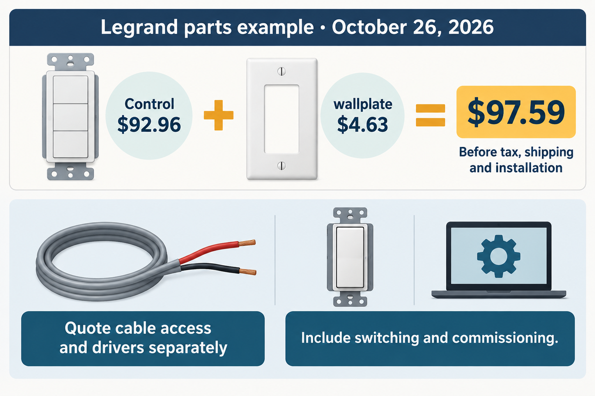
Legrand’s radiant 0-10V model RH4FBL3PW was listed at $92.96 on October 26th, 2026. The wallplate is sold separately. Budget the installation of the retrofit control separately from the hardware cost. Ask competing bidders to quote the same scope of work for controls, drivers, access for new cabling, power switching and commissioning.
The same page lists the RWP26WCC10 wallplate at $4.63. For one control location, the listed parts total $92.96 + $4.63 = $97.59 before tax, shipping or installation. Two identical locations total $195.18 for those parts. Add the contractor’s site-specific cable, driver and commissioning costs to this subtotal. The hardware has an illuminated locator feature; a locator light helps find the switch, but does not identify the dimming interface.
An existing, accessible and compatible driver and control pair favor a controls-only change. In a warehouse with LED high bay fixtures, access equipment and separate zones should be included. For occupied offices with LED panel lights, include disruption and work hours. Outdoor projects require the correct enclosure and environmental ratings.
Finance should compare measured input power and operating schedules before claiming lighting energy savings. Turning a slider halfway isn’t a 50% savings calculation. According to PNNL researchers, the recommendation is as follows:
“requesting dimming curves for all specified 0–10V luminaires”
Specify the lighting zone before ordering
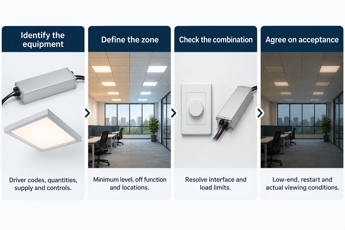
A useful quote request should include the fixture, driver, control model and intended zone behavior. The customer should also state the level of darkness required of the lighting, which areas should be controlled, and if brightness and color are independent. The procurement staff can then identify similar systems, and the installer can evaluate the control and power requirements prior to the equipment arriving on site.
- Identify the equipment. Record driver codes, quantities, supply voltage and existing controls.
- Define the zone. State the required minimum level, off function and control locations.
- Check the proposed combination. Have the supplier and installer resolve interface and load limits.
- Agree on acceptance. Include low-end operation, restart behavior and the actual task or camera conditions.
For a larger system, read our commercial lighting control system guide. If your project includes outdoor flood lighting, send Guangqi Lighting your fixture schedule and control requirements to discuss the specified configuration.
Frequently asked questions
Does Lutron Caseta make a 0-10V dimmer?
Caseta can control a supported 0-10V installation through a specified interface combination.
The PD-10NXD-XX PRO dimmer is compatible with Lutron’s GRX-TVI load interface according to its product listing and requires a neutral when operating drivers or interfaces. That pairing doesn’t make every Caseta device a native analog controller. Match the exact models and wiring instructions when connecting the system.
Can low-voltage lights be dimmed?
Low-voltage lights can be dimmed when their driver or power supply supports the chosen control method; the lamp’s supply voltage alone doesn’t identify that method.
For example, MEAN WELL’s ELG-100-24B has a 24 V rated output and an analog dimming option. Its control adjusts output current to the connected LED load. Match the supply’s output and dimming specifications to the lights; this example doesn’t make an arbitrary low-voltage lamp dimmable.
Does a 0-10V dimmer need a neutral?
Some models need a neutral at the control; others don’t.
Legrand’s RH4FBL3PW is listed without that requirement, while the documented Caseta interface arrangement requires a neutral. The driver’s supply connection is a separate matter. An existing wallbox without a neutral therefore narrows the control choices, but doesn’t by itself rule out every analog dimming solution.
Is 0-10V dimming AC or DC?
The analog dimming signal is DC.
A fixture can still receive AC operating power. Treat the control circuit and supply circuit as separate specifications. The DC 0-10V label describes the command interface, not the mains rating or an assurance that its conductors are safe to touch.
How far can 0-10V control cable run?
Lutron calculates 613 feet in one worked example with a 0.2 V drop allowance, 50 drivers at 1 mA each, and wire resistance of 0.00326 ohms per foot.
That distance follows those inputs and includes the outgoing and return conductors. It isn’t a general cable-length allowance. Longer cable, smaller conductors and more total current increase voltage drop; noise and routing matter too. Use the selected equipment’s cable specification and the actual driver count, especially when electronic off needs a low voltage at the farthest driver.
Can a motion sensor work with 0-10V lights?
Yes, with a compatible sensor and load controller.
For occupancy-based dimming applications, some arrangements combine sensing, a relay and an analog dimming output. Others only switch power. Specify whether vacancy should command a reduced level or turn the zone off, then select the supported control architecture.
Does setting the dimmer halfway save half the energy?
No. Slider position and control voltage don’t establish an equal percentage reduction in input power.
The driver’s curve and the operating schedule determine the result. Use measured watts at the intended light levels when comparing annual consumption. Keep savings from replacing old lamps separate from savings caused by dimming, and include any standby power. Otherwise, the same energy reduction can be counted twice in the project budget.
References & Sources
- PNNL-32949: characterization of 0–10V LED streetlight response historical measured sample.
- ANSI C137.1-2022 public interface-standard summary.
- ANSI E1.3-2001 (R2021) entertainment control scope.
- NEMA JSC 10410-2023 switching compatibility test scope.
- DOE: Understanding LED Color-Tunable Products control-channel functions.
- DOE: Flicker Research temporal light effects and measurement.
- University of Maryland: Division 26 Electrical institution-specific procurement requirements.
Guangqi Lighting’s approach to control selection
This guide connects 0-10V dimmer selection with the driver and lighting-zone details a project needs. Guangqi Lighting uses public technical documentation here to explain procurement and compatibility checks. The cited measurements belong to their research authors, and the named product ratings belong to their manufacturers. No Guangqi laboratory test is claimed in this article.