Get in Touch with GUANGQI



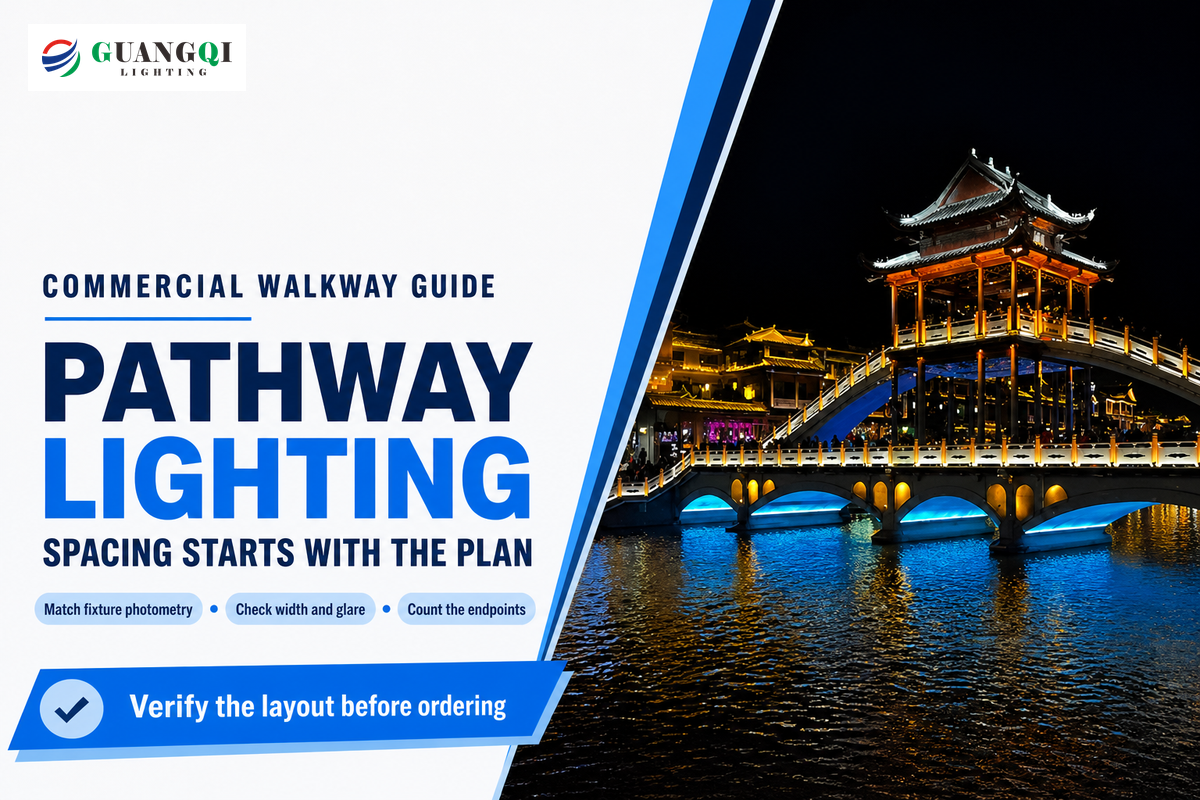
The spacing of lights in a walking route is known as pathway lighting spacing. The distance between fixtures is determined during commercial landscape design by analyzing the selected fixture’s photometry, path geometry and project criteria. Buying lights first and dividing the path length afterwards may result in an uncomfortable glare problem.
Updated October 2026 │ Commercial walkways, gardens and shared pedestrian routes │ Guangqi Lighting
Quick layout brief
- More fixtures don’t automatically create better visibility.
- Specify the exact optic, output and mounting height before comparing gaps.
- Check pavement, pedestrian views and the site boundary separately.
- Count endpoints explicitly: a hypothetical 30 m run at a 6 m maximum gap has 6 positions, not 5.
Set pathway light spacing from the exact fixture’s photometric plan, and then test the layout at night. Check both walkway edges, the gaps between lights and glare. Only after laying out the endpoints of the path and defining the layout, use path length to estimate quantity.
Pathway lighting spacing starts with the fixture
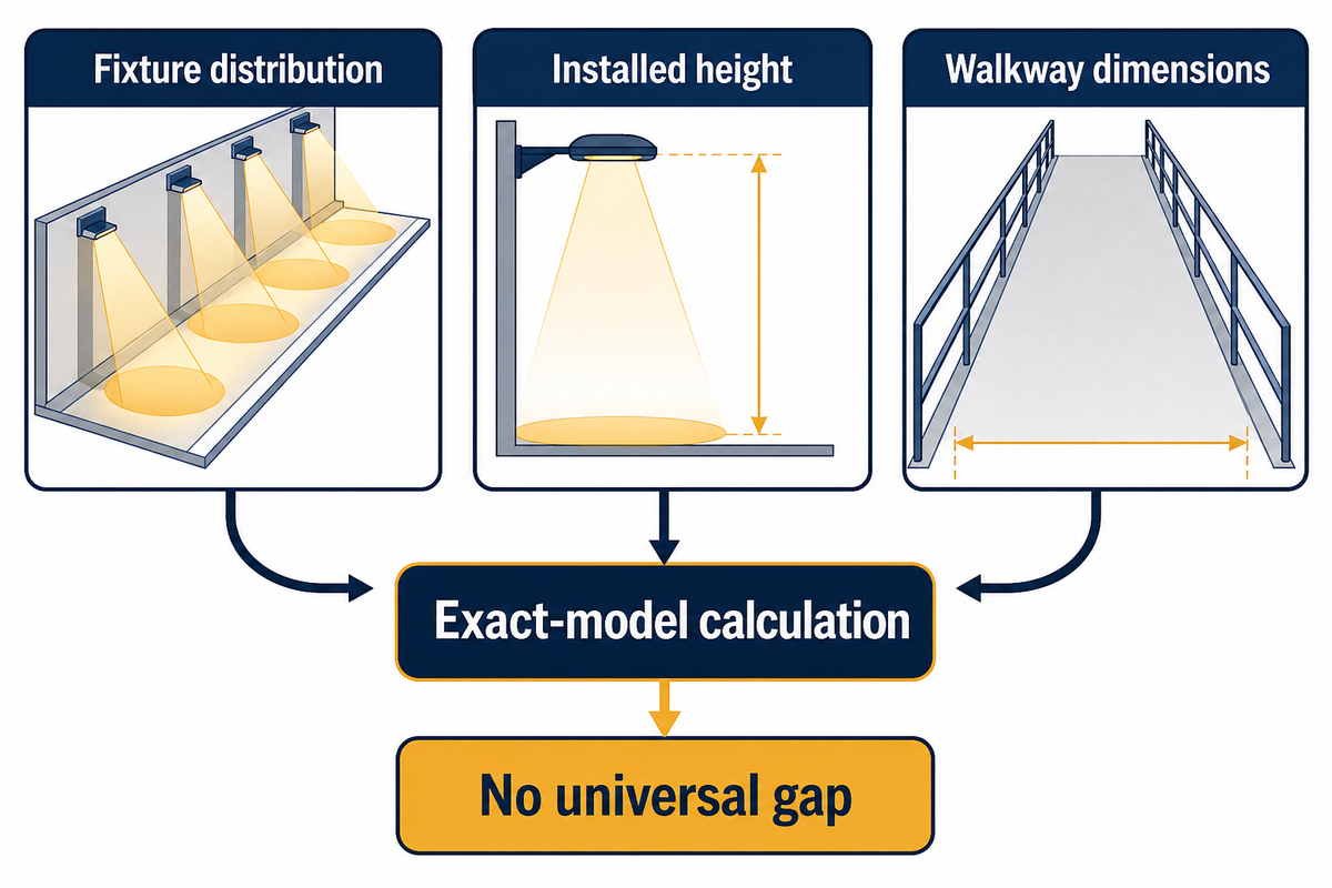
Choose spacing by looking at 3 inputs together: the fixture’s light distribution, its installed height and the walkway’s dimensions. Lumen rating gives the total light output of the fixture and doesn’t show where that light lands. Ask for calculations using the actual model to approve the distance between lights.
How far apart should path lights be spaced?
There isn’t a single distance that approves all commercial paths. A small shielded path light, an asymmetric bollard and a pedestrian pole cast light differently. Even two housings that look similar may use different optics. A supplier’s spacing suggestion becomes useful when it provides the model, mounting arrangement, calculation surface and acceptance criteria.
The U.S. Department of Energy suggests obtaining IES photometry from a qualified independent laboratory or a qualified manufacturer-based laboratory. Its guidance is about product-specific evidence, not a universal number of feet apart.
“Look for photometry in standard IES file format from qualified independent or qualified manufacturer-based laboratories.”
Common mistake: treating a replacement fixture as equivalent because its wattage matches. Keep the proposed positions provisional until the replacement’s distribution is checked. This is particularly important if the model changes after the lighting design has been approved.
Path light spacing is determined by the location of the useful beam, not by the number printed beside lumens. Product descriptions often group together several types of outdoor lighting. Separate decorative markers from lighting fixtures that are meant to serve the walking surface before comparing prices.
Match beam spread and mounting height to the walkway
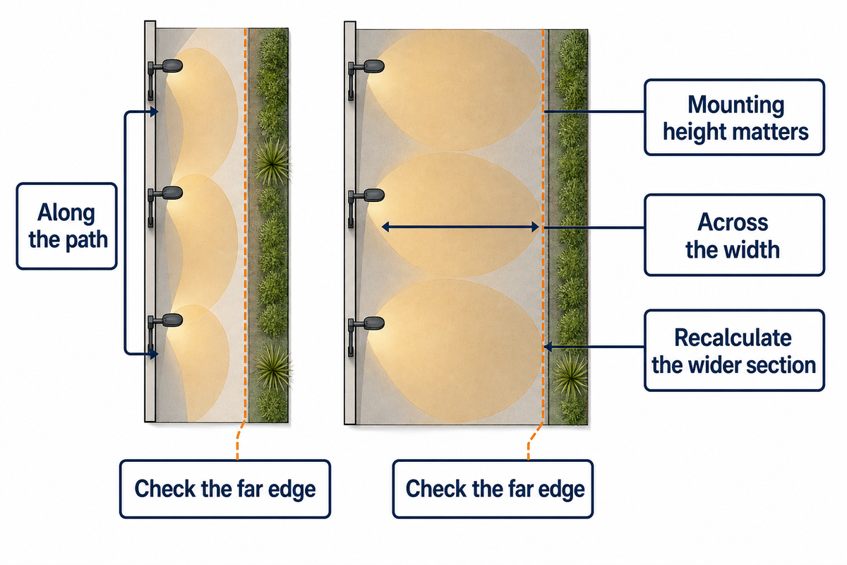
Check 2 dimensions before stretching the gap: how far the beam reaches along the path and if it reaches the opposite edge. Mounting height changes the geometry of the situation. A wider beam footprint may decrease the amount of light on the surface. Taller fixtures therefore also need a recalculation, not an automatic widening.
The Federal Highway Administration’s visibility review mentions glare and uniformity with type and height of fixture. It supports combining these variables. High-pole roadway distances shouldn’t be transferred to low landscape path lighting.
A fixture’s beam spread is a shorthand for its distribution. Ask where its photometric center is from finished grade, not the total height of the decorative housing. Compare landscape fixture families by the surfaces they illuminate, including the far edge and changes in elevation.
Shielded outdoor lighting fixtures direct light downward, but that alone doesn’t address coverage. If the beam from one fixture slightly overlaps the next, ask at what measured level that overlap occurs. Two faint light pools touching on a rendering don’t prove enough light reaches the actual path.
Let’s say there’s a hotel route that widens from 1.5 meters to 3 meters. The owner is intent on keeping a consistent appearance by using the same shorter fixtures throughout. Copying the narrow section’s layout preserves the rhythm, but says nothing about coverage across the wider paving. The designer can compare another optic, a second row or a separate source serving the seating area. Procurement should request those alternatives and their actual quantities. If the wider area requires a different product, note that change in the schedule before it’s set in concrete. Choosing the right housing for curb appeal is acceptable. It’s the unchecked change in width that’s more expensive.
Read a photometric lighting plan before setting spacing
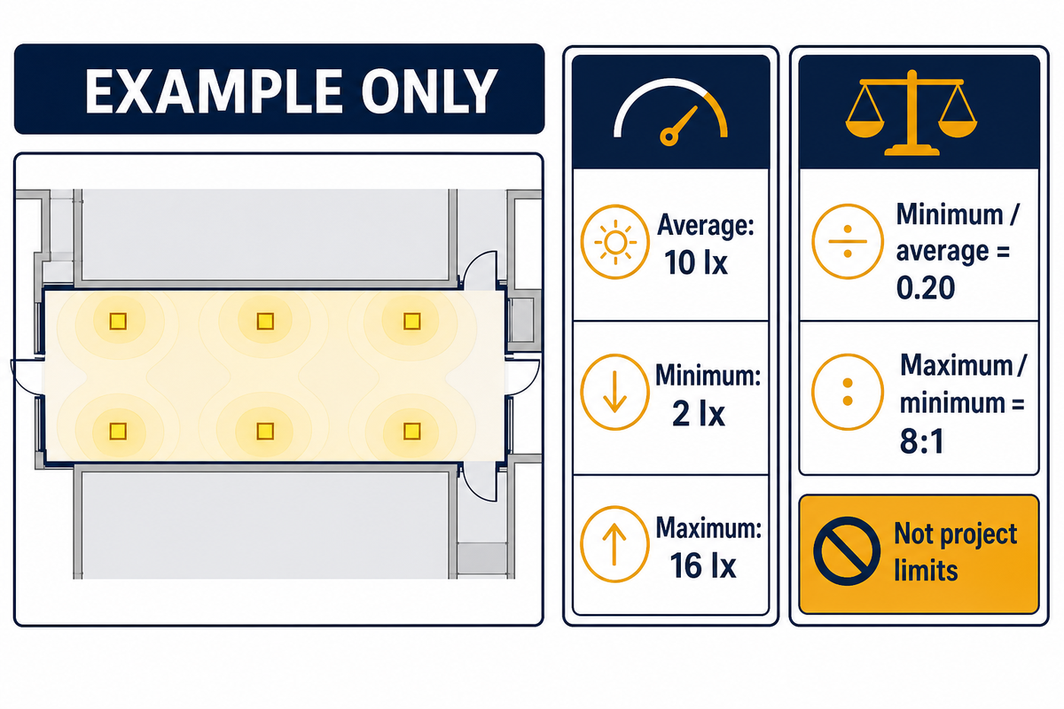
Read the 3 things before accepting the plan: the inputs, calculation surfaces and results. Verify the fixture and height. Examine the minimum and average illumination where people walk. Finally, review the maintenance assumptions. A bright average can conceal a dark edge.
Scottsdale’s local submittal guide calls for horizontal site illuminance and vertical perimeter light-trespass studies, with fixture identities matching the plans and cut sheets. This is a good example of what a checkable lighting submission contains, not a national rule for every property.
Initial results of a modeled new installation are described. Maintained results account for the light-loss factors assumed. Label both results, and make the assumptions for cleaning and replacement of the luminaires visible to the facilities team. Otherwise the owner may approve a calculation that depends on maintenance that hasn’t been budgeted.
Write uniformity ratios in full. For a hypothetical illuminance result averaging 10 lx, with a minimum of 2 lx and a maximum of 16 lx, the minimum/average ratio would be 0.20, and the maximum/minimum would be 8:1. These ratios aren’t conflicting answers, and the example doesn’t describe the values that would define a limit for the project.
Watch the Grid: Calculation-point spacing isn’t fixture spacing. Drawings marked with a regular grid still need to show actual light positions, path edges and obstructions. Have the designer show you the weakest points and explain how they compare to the project criteria.
Choose single-row, staggered or opposite path lights
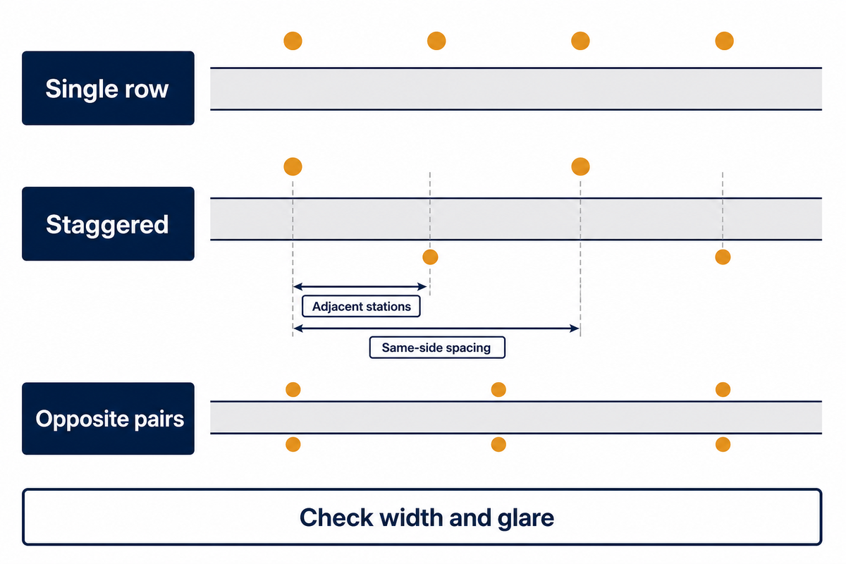
Compare 3 row arrangements using the same fixture and project criteria: single-row, staggered and opposite pairs. The drawing must show the definition of distance measurements. The gap between two adjacent staggered stations isn’t equivalent to fixture spacing on the same side. Confusing labeling can change the quantity ordered.
Should path lights go on one side of the path or both?
Use one side when the selected distribution can serve the required width without unacceptable glare or spill. Compare both sides when one row can’t satisfy the design. The FHWA review recognizes single-sided, staggered and opposite arrangements, but doesn’t establish a universal winner for low path lights. Use the layout variables together instead of choosing a pattern by appearance alone.
| Situation | Candidate arrangement | Check before buying |
|---|---|---|
| Narrow straight route | One row | Opposite-edge minimum and glare |
| Wide open walkway | Opposite pairs | Center overlap and total quantity |
| Two usable planted edges | Staggered rows | Same-side pitch and alternating dark areas |
| Wall beside the route | Wall-mounted plus path lights | Combined operation and shadows |
| Curved path | Individually positioned lights | Inner and outer edge coverage |
| Steps or ramp transition | Dedicated transition lighting | Visible level changes from both directions |
| Seating beside a path | Shielded route and seating sources | Seated-eye views and spill |
| Protected dark boundary | Directed optics or revised route-side locations | Approved exclusion area |
| Mixed pedestrian and vehicle access | Coordinated walkway and driveway design | Separate tasks and physical clearance |
For a geometry-only sketch, alternating stations at 0, 3, 6 and 9 m create a longitudinal station spacing of 3 m, and a same-side spacing of 6 m. The diagonal distance also depends on the separation between the rows. Label the stations and count the symbols; don’t just double the estimate for a single row when you stagger fixtures.
Uniformly placing lights may look orderly by day. It can also create a runway effect at night if exposed sources dominate the view. Keep the visual rhythm only where the calculated coverage and pedestrian view support it.
Keeping spacing consistent can make a layout visually appealing, yet regular spacing ensures neither comfort nor continuous illumination. Mark the lights along the path on the plan, and then let the results justify any exceptions. At a junction, the arrangement should help guide the way without suggesting that a closed service route is the main entrance.
Adjust lights around curves, steps and garden beds
Check each bend from 2 travel directions, then inspect the path edge and any change in level. Irregularities such as flower beds, nearby plants and sudden changes in level can affect an otherwise uniform layout. Keep the fixture outside the required walking space.
Belfast’s lighting strategy explicitly addresses both level changes and lighting columns that obstruct users. Local guidance illustrates why the placement of lighting columns should have regard to mobility and sight loss, as well as ground illumination. Be sure the project designer confirms the applicable clear-route requirements.
When another light is the wrong purchase
Imagine a facilities manager inspecting a dim bend next to a 2 meter garden bed. An installer suggests adding two matching lights. During the proposed night inspection, a mature shrub would block the downward light and an exposed lamp would be visible to a user on the approach. More of the same fixture could add cost while preserving both problems. First establish whether pruning is acceptable, then trial a revised position or shielded optic. Check the approach from both directions with the surrounding landscape lighting operating normally. If the route is adjacent to a bedroom window, consider that view when evaluating the adjustment.
Don’t order the extra light just because a bend looks dark in one picture. The DarkSky and IES lighting principles state that light should be directed where it’s needed at the correct level. Identify the obstructed surface and request a demonstration of the correction. Where ecological review defines an area that must remain dark, change the location or optic within the approved design rather than lighting the vegetation indiscriminately.
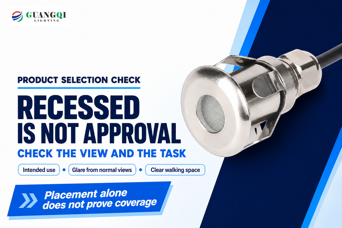
Steps, deck edges and other hardscape features may need a separate light source. If you’re considering recessed landscape fixtures, check the intended use and glare from normal viewing positions. Just because a fixture is set into a paving surface doesn’t make it designed to illuminate walkways or guide your steps across a level change.
Price the fixture count and installation scope together
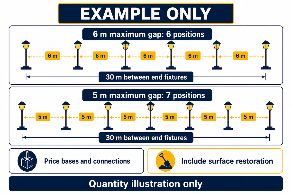
Estimate the number of luminaires from the limits defined by the layout and then compare installation scope line by line. On a hypothetical 30 m straight run, reducing the maximum gap from 6 m to 5 m changes one row from 6 to 7 positions.
How many lights do I need for my walkway?
For a straight single row with fixtures at both endpoints, use N = ceil (L/S) + 1, where L is the distance between the end fixtures, S is the proposed maximum gap, and ceil means round up to the nearest whole number. If the endpoints move, adjust L; if the route branches, count each junction only once.
For a hypothetical straight 30 m route with a fixture at both endpoints and a maximum 6 m gap, the quantity is ceil(30 / 6) + 1 = 6 fixtures in one row. In this case, we would need ceil (30/6) + 1 = 6 fixtures in a single row to fill this route. If the maximum gap is 5 m, we would need ceil (30/5) + 1 = 7 fixtures. An evenly distributed 32 m route with a maximum gap of 6 m would require 7 fixtures and a real gap of 32/6 = 5.33 m.
| Quotation item | Option A | Option B |
|---|---|---|
| Distance between end fixtures | 30 m | 30 m |
| Proposed maximum gap | 6 m | 5 m |
| Number of intervals | 5 | 6 |
| Fixture positions | 6 | 7 |
| Endpoint assumption | Both ends included | Both ends included |
| Fixture/optic selection | Price exact scheduled model | Price exact scheduled model |
| Bases and connections | Price 6 complete positions | Price 7 complete positions |
| Cable and trenching | Measure actual route and branches | Measure actual route and branches |
| Surface restoration | List paving/planting affected | List paving/planting affected |
| Commissioning | Include controls and night checks | Include controls and night checks |
| Approval status | Quantity illustration only | Quantity illustration only |
In Option A finance sees one fewer fixture, and requests the saving. The contractor needs to understand whether this removes a base, a connection and any restoration work, or just a luminaire. The designer needs to understand whether either layout works. Request separate fixture, civil work and commissioning amounts before comparing totals. Seven cheaper fittings may cost more than six alternatives, installed, if their connection work or restoration scope is different; the converse may also be true. The correct comparison is the accepted installed design, with the same exclusions priced, rather than an unsubstantiated price per meter.
Wheat Ridge’s photometric-plan checklist illustrates the connection between a location plan, fixture schedule and product sheets. For low-voltage lighting, also align cable routes with voltage checks for long cable runs. Don’t fix an electrical output problem by casually reducing gaps.
Test at night with the 3-View Layout Proof
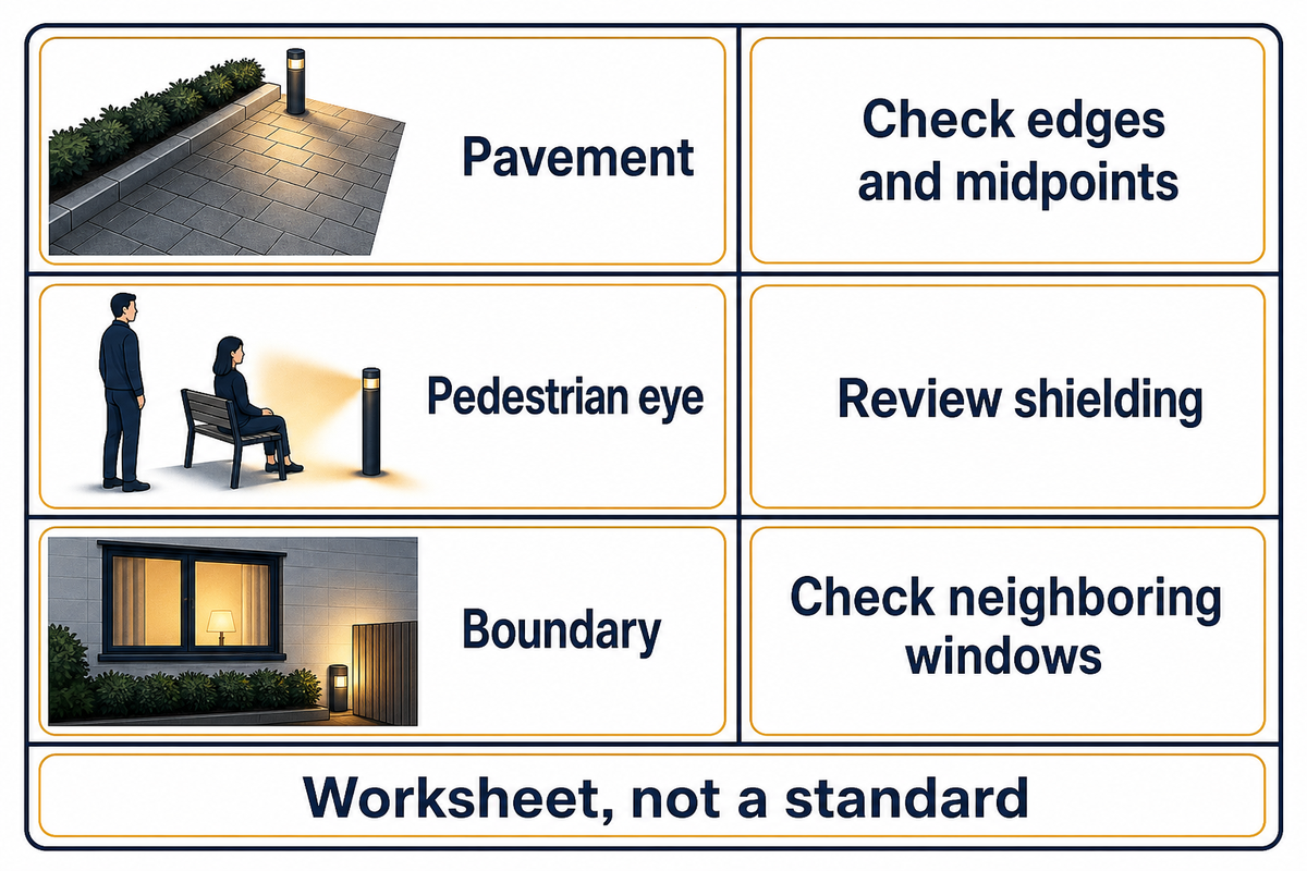
Use 3 views to record a trial layout: pavement, pedestrian eye level and the site boundary. Compare measured results to project criteria, and note your findings separately. This worksheet, developed by this author, is designed to organize a nighttime inspection. It is not a recognized standard, certification or substitute for the designer’s acceptance process.
A 2021 study by Ulrika Wänström Lindh and Annika K. Jägerbrand looked at three pedestrian roads in Sweden, and showed that perceived uniformity differed from calculated horizontal uniformity. Other aspects, e.g. tree placement and shadows, also played a role. The small qualitative study does not establish a transferable spacing or prove how all users will respond.
| View | Hypothetical observation | Required follow-up | Decision owner |
|---|---|---|---|
| 1. Pavement | Far edge looks darker midway between positions 2 and 3 | Measure/check the edge and midpoint against the project minimum; compare revised optic or position | Lighting designer |
| 2. Pedestrian eye | Visible source is uncomfortable when approaching the seating area | Review shielding from standing and seated views; include intended-user feedback | Designer and facilities manager |
| 3. Boundary | Light reaches a neighboring window at normal night output | Check the applicable boundary criterion and trial controlled distribution | Designer and property owner |
GOV.UK’s planning guidance notes that older or visually impaired users may need different light levels, contrast and controls, while glare sensitivity increases with age. Apply that user-needs consideration without treating UK planning guidance as a US code. One observer’s comfortable view does not reflect the requirements of all pedestrians.
- Set the operating scene. Run nearby building lights and the proposed normal output together.
- Walk the route. Inspect both directions, transitions and seated views.
- Record and measure. Separate visual observations from instrument readings and the applicable limits.
- Trial the correction. Change one relevant variable, document it and obtain project acceptance before permanent work.
Photos show the relative positions and symptoms of subjects, but a camera’s exposure can alter how we perceive brightness. Keep measurements and settings in the record. If motion sensors or dimming create a lower night scene, inspect that scene too; the full-output demonstration alone is insufficient.
Review the property at night with its usual activity present. A well-lit photograph of empty paving may miss the lighting effect seen from a restaurant table. If lights become the dominant objects in that scene, discuss shielding prior to adding output. The desired ambiance belongs in the brief, alongside the need for light to guide pedestrians along main walkways.
Request the supplier’s layout deliverables
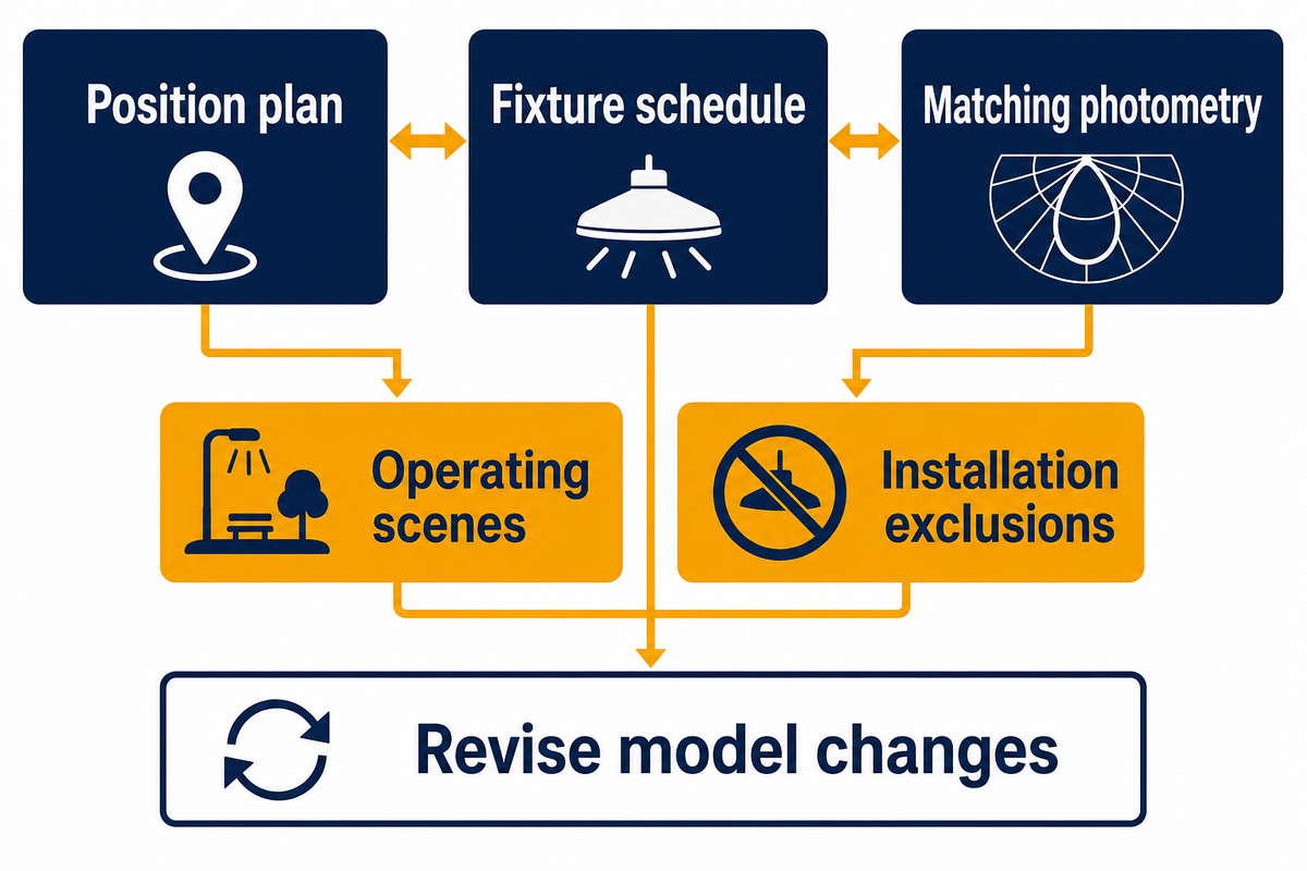
Request 3 linked files before releasing the order: the position plan, fixture schedule and matching photometric information. Add the operating scenes and installation exclusions to the quote. This allows a prospective customer to compare offers and consider optics, mounting height and civil work, without changing these hidden constraints.
Scottsdale’s document-matching requirements illustrate the many ways a rendered image is inadequate. The following brief is a starting point; the numerical entries indicate the hypothetical route and must be replaced with actual project dimensions.
| Parameter | Recommended range | Why it matters | How to verify |
|---|---|---|---|
| Route dimensions | Example only: 30 m long; 1.5–3 m wide sections | Width changes distribution needs | Dimensioned site plan |
| Trial gaps | Example only: 5–6 m, subject to calculation | Quantity changes from 7 to 6 in one row | Marked positions and results |
| Mounting height | Model-specific, in m above grade | Sets optical geometry | Schedule and matching photometry |
| Light output and controls | Project-specific lumens and dimming settings | Defines the operating scene | Driver/control compatibility |
| Acceptance criteria | Project-specific lx or fc; ratios named | Prevents ambiguous approval | Designer-approved calculation brief |
| Maintenance assumptions | Project-specific light-loss factor | Connects results to upkeep | Written cleaning/replacement basis |
Don’t accept an alternative model with the original plan number without a revision. Guangqi’s service page outlines IES-file requests and project layout support. When you request a project lighting layout, send the site drawing and requested operating hours along with boundary conditions; inquire about the files and revisions provided for the product being requested.
What current outdoor lighting guidance changes for buyers
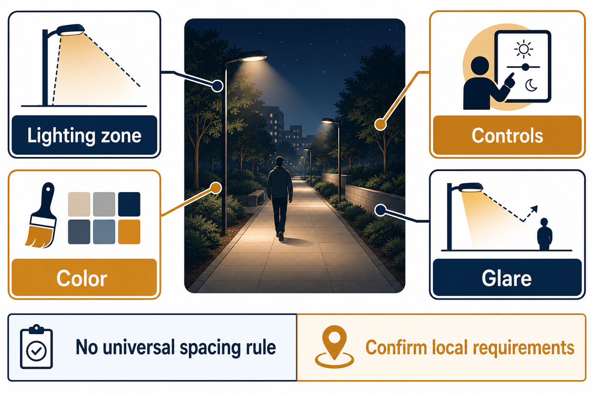
For an October 2026 design brief, cite the guidance edition and the project lighting zone instead of requesting an unspecified “standard layout.” The public RP-43-25 description covers 4 subjects: lighting zones, color, controls and glare. Its scope doesn’t provide a general rule for pathway light spacing.
The Illuminating Engineering Society’s (IES) public description of RP-43-25 references revised lighting zones, colors, controls and glare content. Have the designer explain the applicable guidance and local requirements for the site. A recommendation shouldn’t be considered a legal obligation simply because it’s published.
For the buyer, the main change is the brief: explain whether the route serves a quiet garden, an active entrance or a mixed-use shared space. Identify the surrounding ambient light and the hours of each scene. Energy efficiency should be evaluated within those tasks, so reducing energy consumption does not simply move an unresolved visibility problem into a dimmed period.
Use path lighting, along with other features, to compose the nighttime landscape. The outdoor experience includes entrances and seating, as well as the surrounding environment that’s visible to the public beyond the roadway. To ensure your path remains understandable when nearby decorative lights switch off, ask for that operating scene to be included in the review.
Key takeaway
Approve the fixture, layout and operating scene together. A 30 m quantity calculation can help compare quotes; only the project calculation and site acceptance process can justify the installed spacing.
Frequently asked questions about pathway lighting
Are LED path lights dimmable?
Dimming depends on the exact fixture, driver and control system.
Ask the supplier to match the driver and control method, including the permitted operating range. A lower setting changes the light reaching the walkway. Have the designer check the scheduled night scene as well as full output, and confirm how controls return to the required level. An integrated LED label alone does not establish compatibility or suitable coverage at reduced output.
Are solar path lights a good choice?
Solar can suit sites where bringing in cable is difficult, provided the model meets the operating requirements.
The power source does not determine ideal spacing. Request photometry at the scheduled output and the site’s battery and solar sizing assumptions. Shade, seasonal conditions and operating hours belong in that assessment. A bright demonstration just after sunset cannot establish performance throughout the night. Compare the complete lighting solutions on the required service period, not simply on whether they need a trench.
Can I mix different light styles?
Yes, when each style serves a defined task and the combined layout is checked.
A low path light beside planting, a bollard on an open route and a separate step light can serve different surfaces. Keep their color appearance, output and glare under review. Equal wattage does not create matching coverage. Request a calculation using each exact model, then look at how the pools of light meet where one fixture type gives way to another.
Are there too many pathway lights?
Possibly; quantity alone cannot establish quality.
Check glare, excessive contrast and spill. Trial revised output or optics before removing fixtures that cover an otherwise dark section of the route.
What metal finish lasts the longest for outdoor path lights?
There is no universal winner for every exposure.
Compare documented materials, finish, cleaning requirements and warranty exclusions against moisture, salt and maintenance conditions. Ask how the specified finish is intended to resist corrosion and wear.
References & Sources
- U.S. Department of Energy: Outdoor Area Lighting (2008; photometric methodology).
- Federal Highway Administration: Roadway Lighting research review (geometry and visibility; road-specific limits not transferred).
- Scottsdale: Exterior and Site Lighting (local submittal example).
- Belfast City Council: Luminous City (2020; accessibility and placement).
- DarkSky and IES: Five Principles for Responsible Outdoor Lighting.
- Wheat Ridge: Photometric Plan checklist (local documentation example).
- Wänström Lindh and Jägerbrand: Perceived Lighting Uniformity on Pedestrian Roads (2021; exploratory study).
- GOV.UK: Light pollution planning guidance (user needs and ecological considerations).
- Illuminating Engineering Society: RP-43-25 public description (scope only).
Examples and worksheets in this article are illustrative design aids based on public sources. They aren’t Guangqi customer measurements or approved installation designs.