Get in Touch with GUANGQI



Updated October 2026
Quick specification priorities
Define controlled load and zone, identify driver interface, document each gateway function, agree on witnessed acceptance before ordering.
A lighting control panel can switch a warehouse aisle, dim an office perimeter, or coordinate an architectural lighting scene. Choosing the enclosure is only part of the purchase. The driver, circuit schedule, control logic and gateway must support the same required behavior, and the commissioning records must show that behavior at the installed lights.
A lighting control panel is an assembly that manages lighting operation through one or more of relays, controllers or lighting interfaces. Specify electrical limits and control functions separately, and then verify the installed circuit, gateway mapping and sequence of operations.
Key takeaways
- A shared protocol name doesn’t guarantee complete interoperability or physical light feedback.
- A relay’s running-current rating does not alone qualify an LED-driver population.
- Driver dimming, complete off, address capacity and independently controlled zones are separate requirements.
- Approved purchasing documents and final commissioning records belong to different stages.
What Is a Lighting Control Panel?
A lighting control panel manages how lighting operates. A relay panel mainly switches loads; an addressable controller can manage individual gear or groups. The assembly schedule determines whether electrical distribution and protective equipment are included or located elsewhere.
What is LCP in electrical?
LCP can mean a lighting control panel. Confirm the drawing legend and schedule: the abbreviation alone does not tell you whether the cabinet contains relays, a controller, distribution equipment or a combined assembly. Match that schedule to the specification and compare suppliers.
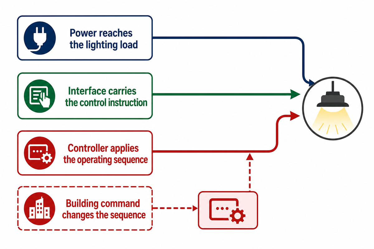
Separate three paths: power reaches the lighting load, an interface carries the control instruction, and the controller applies the operating sequence. A building automation command can change the sequence without being the electrical source supplying each fixture. That distinction helps building owners identify which contractor owns a fault or incomplete integration.
OSHA 1910.303 addresses installation instructions and protective-device coordination in its applicable United States workplace context. A switching device and equipment intended to interrupt fault current have different qualification questions. Evaluate the protective device schedule of the assembly before approving a relay output for the specified load.
“Listed or labeled equipment shall be installed and used in accordance with any instructions included in the listing or labeling.”
Common mistake: It is a common mistake to think every LCP cabinet sold contains branch circuit protection. Identify the protective requirements upstream, and check what is included in the cabinet. A combined assembly can be appropriate if the drawings show protective devices and loads that are controlled.
Components Inside a Lighting Control Panel
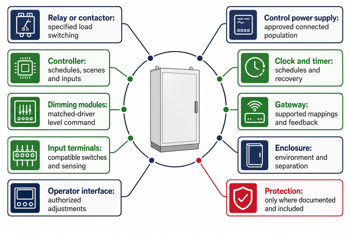
Lighting control panel components should be identified by function, model number and interface. Relays switch loads. A controller interprets commands. Dimming modules send level instructions. Inputs, power supplies, and gateways help perform those functions. The component list becomes useful when a rating is assigned and verified for each component and a commissioning responsibility is assigned.
| Component | Role | Request in the submittal |
|---|---|---|
| Relay or contactor | Switches the specified lighting load | Load category, voltage, permitted LED driver population and operation |
| Controller | Processes schedules, scenes and inputs | Exact model, firmware, stored logic and backup method |
| Dimming modules | Transmit a level command to matched drivers | Protocol, channel population, minimum output and off behavior |
| Input terminals | Receive wall switches and occupancy sensing | Supported signal, low voltage inputs or required interface |
| Control power supply | Powers compatible controller and bus equipment | Output rating, connected population and replacement reference |
| Clock and timer | Apply daily, holiday or astronomic schedules | Time zone, clock retention and recovery after power loss |
| Gateway | Maps lighting functions to other building systems | Object/point list, protocol version and supported feedback |
| Enclosure and separation | House the approved assembly | Environment, access, line/low-voltage segregation and labels |
| Protective equipment, where included | Provides documented protective functions | Circuit breakers/fuses and assembly ratings; never inferred from relay count |
| Operator interface | Allows authorized monitoring or adjustments | Manual override, touchscreen access and permitted settings |
A momentary wall switch can request a timed override; a maintained switch has different input behavior. Also, a relay that needs power to hold its state is different from one that can latch. The supplier should describe the device and its behavior with respect to power loss. You can’t assume that each manual input uses the same logical construct.
Low voltage is a signal or supply description. Don’t assume that every terminal is interchangeable. The installer needs the approved drawings and the manufacturer’s instructions for the selected assembly. Cabinet access and separation between control wiring and power circuits remain part of the electrical design, even when the user interface is simple.
For smaller applications, remote-switch load and control limitations help distinguish a standalone switch from a coordinated multi-zone system. A panel is valuable when the requirement requests functions beyond that switch’s documented functionality.
Common mistake: accepting a brochure’s feature list without exact modules. Request the controller, gateway and driver references in the same revision; an omitted interface can change installation costs and the permitted operating sequence.
LED Circuits, Relay Ratings, and Expansion
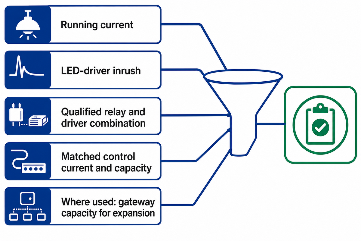
Evaluate circuits from selected loads and switching equipment. Confirm control capacity. A number of factors may limit the ability of a control to carry current or support additional functions. Running current, LED-driver inrush, qualification of relay, and analog control current, and future system expansion to accommodate additional loads and addressable space, are a few of the many constraints to consider. Where a gateway is used, future expansion requires sufficient gateway capacity. A single advertised amperage cannot establish all of those conditions.
An LED driver’s turn-on behavior can differ substantially from its steady load. Lutron’s 0–10 V application guidance explains that relay rating, control-current capability and inrush can each constrain a connected population. Its product-specific evidence should be read with the selected control and driver documents. A general multiplier can’t qualify a different combination.
A 120 V AC driver specification is applicable only to that supply and product. It doesn’t determine suitability for a different supply voltage. “120V compatible” means different things depending on which driver, load category and panel model it’s being used with.
Circuit-to-Control Proof Ledger
A Circuit-to-Control Proof Ledger links each controlled load and zone to the component evidence needed for procurement and acceptance. This is an editorial project template; responsible-party entries are examples, and ownership must be assigned in the project contract.
| Record field | Information to capture | Responsible party |
|---|---|---|
| Circuit and supply | Drawing reference and verified AC supply | Electrical designer/contractor |
| Protection | Upstream protective device and assembly compatibility | Electrical designer |
| Switched load | Fixture quantity, exact LED driver and running current | Luminaire supplier |
| Output | Relay/module channel and approved driver population | Control-panel supplier |
| Control zone | Which occupied space or scene follows that output | Controls designer |
| Dimming interface | 0–10 V source/sink, DALI addressing or DMX mode | Controls integrator |
| Control-current limit | Matched driver current and controller capacity | Control-panel/driver suppliers |
| Emergency classification | Approved role and separate test requirements | Responsible life-safety designer |
| Future provision | Usable outputs, bus capacity and point allowance | Owner and designer |
| Revision and evidence | Compatibility document, date, exact firmware | Submittal coordinator |
Consider a layout with 6 independently switched zones and 2 planned zones. The channel schedule would need 8 controllable outputs if each zone required a separate output. This math only creates a functional requirement. It doesn’t size circuit breakers, wire, relays or an LED driver population; that’s an equipment and design check.
“Spare capacity” requires the same level of detail. A vacant position in an enclosure may still require another module or an available bus. Before a retrofit, request access to the existing drawings and configuration files. Describe which future lighting loads the upgrade must support instead of selecting an arbitrary reserve percentage.
Common mistake: dividing a relay’s amperage by a nominal bulb wattage and calling the result an approved LED count. Request documented switching compatibility and the relevant control-current limit. Qualified installation and testing follow the approved design.
DALI, 0–10 V, and DMX Control Interfaces
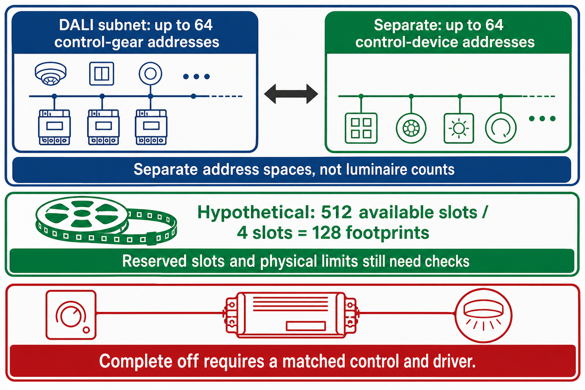
Choose a lighting interface from the required behavior: switching, grouped dimming, individual addressing, dynamic effects or diagnostics. DALI, 0–10 V and DMX lighting handle those tasks differently. The project must define driver compatibility, address or slot requirements, complete-off behavior and available feedback before the panel’s dimming capabilities can be accepted.
| Control approach | Useful function | Evidence required | Selection limitation |
|---|---|---|---|
| Relay switching | On/off circuit or zone | Qualified load switching | Dimming and feedback require additional equipment |
| Contactor switching | Simultaneous control of selected circuits | Correct poles, coil/control interface and load | A single command can cover several loads; zone count still matters |
| 0–10 V dimming | Analog level for a wired group | Complementary source/sink and control current | Minimum level is not automatically complete off |
| Electronic-off 0–10 V pair | Complete-off function where supported | Both control and driver support that function | A generic dimmable label proves neither pairing nor final response |
| DALI individual address | Addressable control gear | Gear addresses and compatible control implementation | One luminaire may contain more than one gear address |
| DALI group | Shared command to selected gear | Group assignment and operating sequence | Group control does not add physical gear-address capacity |
| DALI control device | Sensor or input device | Separate device-address and bus-power capacity | Device addresses are distinct from gear addresses |
| DMX fixture mode | Dynamic color/effect channels | Actual mode footprint and starting slots | A fixture can consume multiple slots |
| DMX universe | Budget for transmitted data slots | Slot allocation, interfaces and electrical-network design | 512 slots does not mean 512 connected luminaires |
| BACnet integration | Mapped objects/properties across systems | Exact PICS, writable functions and integration responsibilities | A gateway cannot create feedback the downstream equipment never measures |
The DALI Alliance Key Feature Overview describes up to 64 control-gear addresses and 64 control-device addresses on a subnet. Those are separate spaces. A fixture containing multiple addressable drivers can consume multiple gear addresses; sensors and input devices use the control-device space. Count implemented gear and devices before stating an address limit equals luminaire quantity.
DMX capacity is measured in data slots. ESTA’s revision discussion notes that most products transmit 512 data slots and that fewer slots may be sent, while its published-document list identifies ANSI E1.11-2024 as the current listed revision. A hypothetical 4-slot fixture mode gives 512 ÷ 4 = 128 non-overlapping footprints in a fully available universe. Other reserved slots decrease that number, and the physical limitation of the network makes further checking necessary.
Analog 0–10 V requires closer matching than its simple label suggests. Source/sink role and control-current capacity affect compatibility. Complete off also depends on the pair. ETC’s support guidance distinguishes ordinary low-end dimming from drivers and controls that support dim-to-off, while Lutron describes electronic-off support as a joint control-and-driver requirement. There are no field wiring shortcuts that replace those specifications.
The January 2024 0-10 V streetlight study summary by DOE reports on testing of 23 LED streetlights and notes variation in driver performance. That sample is not an indoor-panel defect rate. It is a practical reason to agree on acceptable measured dimming behavior instead of treating a requested percentage as identical light output across products.
Common mistake: selecting an interface from its name alone. A 0–10 V pair, a 64-address DALI gear space and a 512-slot DMX universe need different records. Verify the required operating result with the actual drivers and fixture modes.
Fixture mode and color behavior also need to be integrated for architectural projects. Our guide to RGBW facade control and specification risks provides application context for those choices.
Protocol Gateways: Map Commands, Feedback, and Ownership
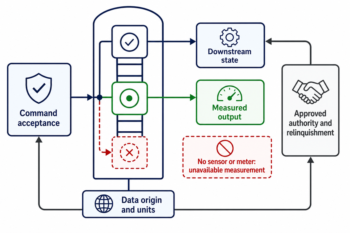
A protocol gateway maps supported functions between systems. The necessary mapping should be documented point by point. In general, commands should be separated from acknowledged state, device status and measured light output. The hardware and firmware determine which functions exist, how unavailable data are reported and which controller retains authority when commands compete.
BACnet is used to connect lighting with other building systems. The BACnet Committee’s explanation of PICS states that the manufacturer’s Protocol Implementation Conformance Statement (PICS) is evidence of implemented capabilities. PICS specify supported objects, writable properties, and constraints. To obtain PICS, contact the manufacturer with your specific model and firmware. Check each required writable property against the corresponding PICS; define each measured value in the project point schedule.
Gateway Capacity and Behavior Schedule
A Gateway Capacity and Behavior Schedule captures each required mapping, its evidence, command authority and expected behavior during communication loss.
| Field | Project-specific entry |
|---|---|
| Identifier | Zone, luminaire/gear address and drawing reference |
| Capacity | Available addresses, independently controlled outputs, mapped objects and licensed points |
| Function | Switch, dim, scene, alarm, energy reading or other expressly required function |
| Object or register | BACnet type/instance/property or alternative exact mapping |
| Value convention | Units, permitted range, scale and meaning of an off command |
| Direction | Command, status, alarm, or measured value; read-only versus writable |
| Authority | Local switch, schedule, occupancy logic and building-system arbitration |
| Evidence | Command acceptance, downstream state and measured output recorded separately |
| Unavailable data | Stale-value indication, absent sensor and communication-loss behavior |
| Recovery | Approved restored-state and relinquishment sequence |
| Version and owner | Exact hardware, firmware, mapper and responsible commissioning party |
It’s possible that a returned dimming value might indicate the controller requested a particular level, rather than measured illuminance. An energy usage figure might be estimated from operation, or come from a dedicated meter. Have the supplier determine data origin and units and indicate availability. If the installation has no relevant sensor or meter, the gateway should not present the field as a measurement.
ORNL’s BACnet driver reference also illustrates why relinquishing a command matters: an active priority can remain in effect until released. Specify the project’s approved arbitration and restoration behavior, then witness it. A successful write doesn’t necessarily indicate that a local switch has regained control.
A useful counter example to easy integration claims is found in the DOE case study: St. Paul Lighting and HVAC Case Study. The study reports that the lighting network used BACnet, but its vendor needed firmware and other modifications to communicate with the HVAC controls network. The building employed a constant air volume system, and HVAC savings weren’t realized. Shared communications and a dashboard cannot guarantee the desired building outcome.
Common mistake: approving “BACnet gateway included” without the mapping and responsibility schedule. Require the promised switch, dim, status and alarm functions to be demonstrated on the specified versions. Missing feedback should be recorded as unavailable, not converted into a reassuring display.
Integration Requirements and Local Control
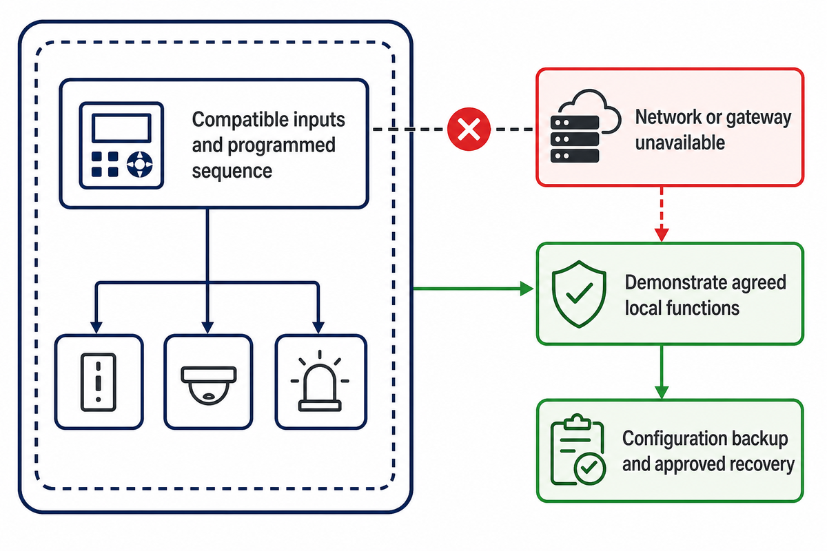
Lighting integration should specify where each function runs, and what continues to operate in the absence of a network or gateway. Occupancy sensors, daylight harvesting, local wall stations or wall switches, and schedules may have different dependencies. The approved sequence must describe local operation, overrides and recovery, while access permissions and software maintenance need separately assigned owners.
An office perimeter can use daylight-based dimming while an internal meeting space uses occupancy sensing and manual scene selection. Multiple lighting zones need separately identified inputs and operating sequences. A warehouse may require predictable switching before staff enter an aisle. These are design scenarios, not proof that one controller supports all the functions. The supplier must show how its inputs, programmable logic and connected lighting implement the required sequence.
A stand-alone controller may be appropriate when local behavior is the requirement. For a networked installation, ask whether the controller stores schedules locally, which functions depend on an external server, and how an authorized operator can restore configuration. Clock retention, backups and replacement procedures affect building operations long after initial commissioning.
The NIST building-systems cybersecurity programme includes lighting and treats security as a lifecycle concern. Record who approves network connections, grants remote-service access, maintains firmware and retains configuration backups. Command precedence inside a lighting system and permission to access that system answer different questions.
DLC’s 2026 retrospective offers additional information on lighting/HVAC integration. If reducing energy consumption is a project objective, define the baseline, operational schedule and measurement method before comparing energy efficiency claims.
Exterior networks have additional application constraints. The smart street lighting specification guide addresses these. The capability of a panel should be aligned to the actual environment.
Common mistake: calling a system “local” because it has a wall station. Have the supplier demonstrate the agreed local functions during a network interruption, show unavailable information and explain the return to normal control. Witness those agreed conditions.
Commissioning: Prove Behavior Before Handover
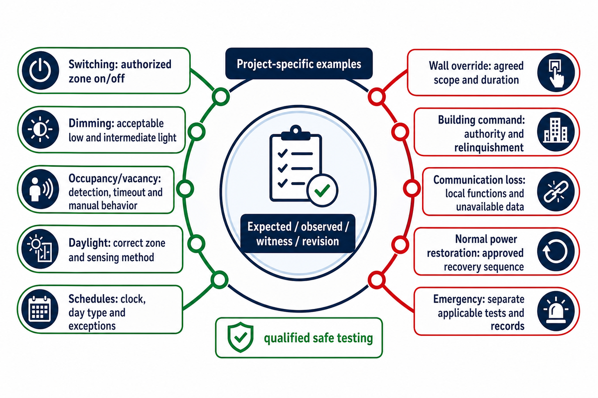
Commissioning confirms that lighting operates as specified. It should connect each test to a defined expected result, an observed result and a responsible witness. A circuit switching once is insufficient evidence for sensor calibration, dimming response, gateway relinquishment, communication recovery or the separately approved emergency-lighting scheme.
DOE/PNNL’s Selecting Lighting Control Systems guide relates objectives, system capabilities and record requirements. Use that logic to establish acceptance criteria before ordering. The approved submittal defines the proposed equipment and behavior; final configuration, as-built schedules and witnessed records describe what was delivered.
10-Event Commissioning Witness Record
A 10-Event Commissioning Witness Record captures expected and observed behavior, records the accepted configuration revision and identifies responsible witnesses.
| Event | Evidence to witness | Retained fields |
|---|---|---|
| Switching | Required zone follows each authorized on/off command | Expected / observed / witness / revision |
| Dimming | Agreed low-end and intermediate levels produce acceptable light | Expected / observed / witness / revision |
| Occupancy or vacancy | Detection, timeout and manual behavior match the sequence | Expected / observed / witness / revision |
| Daylight harvesting | Correct zone responds to the approved sensing/target method | Expected / observed / witness / revision |
| Schedules and holidays | Clock, day type and exceptions produce intended operation | Expected / observed / witness / revision |
| Wall override | Local manual switches obey agreed scope and duration | Expected / observed / witness / revision |
| Building-system command | Command, authority and relinquishment work as specified | Expected / observed / witness / revision |
| Communication loss | Selected local functions and unavailable-data indication match design | Expected / observed / witness / revision |
| Normal power restoration | Approved normal-lighting recovery sequence is observed | Expected / observed / witness / revision |
| Emergency interface | Approved emergency design has its own applicable tests and records | Expected / observed / witness / revision |
The 10 categories of testing are an example, not a universal regulatory test procedure. The project team sets the conditions, tolerances and safe test method. Lighting controls should be configured and tested by qualified personnel under the approved electrical and operating arrangements. Under no condition should a system occupant be required to investigate an issue by opening a live enclosure or bypassing protective equipment.
Emergency and egress lighting need their own applicable design and acceptance records. The DALI Alliance’s self-contained emergency-lighting overview distinguishes functional tests from duration tests. A normal-lighting restoration demonstration cannot establish battery duration, emergency control compliance or the required illumination along an escape route under applicable project rules.
For a representative office zone, witness the occupied setting, the absence sequence, manual intervention and the agreed return to automatic operation. For an architectural dimming zone, examine the approved light response at the specified levels. A successful software command and a satisfactory occupied environment are separate observations; both belong in the record when required. Both should be documented when necessary.
Common mistake: treating sensor installation as sensor commissioning. Location, calibration and the operating sequence affect occupant acceptance. DOE’s lighting checklist explicitly calls for commissioning guidance, a maintenance manual and staff training; retain those deliverables with the final system configuration.
Compare Suppliers with a Project-Specific RFQ

Compare lighting control panel suppliers against the same circuit, interface and commissioning requirements. Ask for the current model, exact module schedule, documented compatibility and gateway mapping. Break down the commercial offer into equipment, programming, integration, witnessed testing and handover support. An inexpensive cabinet price shouldn’t obscure missing responsibilities in the project.
A request for quotation should allow the supplier to identify a conflict prior to manufacturing. Provide the approved zone schedule, driver list, intended supply, dimming behavior, building-system interfaces and emergency scope. Request explicit exceptions. The ability to customize an enclosure is useful only when the resulting assembly and its components have the necessary documented suitability.
Before-order evidence
- Current model, module schedule, controller and gateway firmware references.
- Electrical ratings, protective arrangements and exact driver/control compatibility.
- Interface capacity: separately document 0–10 V current, DALI gear/device addresses or DMX slot budgets where applicable.
- Approved operating sequence, object/point mapping and dependency/failure behavior.
- Installation, integration, access-security and commissioning responsibilities.
Final-handover evidence
- As-built circuit/zone records and accepted configuration revision.
- Witnessed functional results and resolved exceptions.
- Approved emergency-lighting records, where within scope.
- Backup files, operating instructions, staff training and service contacts.
Evaluate product lifecycle and performance when considering the appropriateness of a product. A product listing may change status or be removed but a result or copy may remain visible. Confirm availability, replacement support and software access with the supplier when the purchase is placed. Modular construction and flexibility do not establish continued support by themselves.
Claims about installation efficiency, energy savings or significantly reduced energy consumption need a stated scope and evidence. Request the baseline and included work, then assess the same deliverables in lighting solutions. Neither a manufacturer’s certificate for a different assembly nor a third party’s patent qualifies your panel.
To widen your supplier shortlist, compare control-system suppliers and their project scope, then apply the same evidence schedule. Commercial electrical design and site acceptance remain project responsibilities.
You may approach Guangqi Lighting with your circuit and control brief. For a broader system, consider lighting control systems and request confirmation of the exact equipment and deliverables proposed for your case.
Discuss your circuit and control requirements
Common mistake: approving equipment before agreeing who configures the gateway and witnesses its results. Price the required integration and handover work explicitly. Unassigned responsibilities can leave a complete enclosure with an unfinished gateway mapping or an untested operating sequence.
Lighting Control Panel FAQ
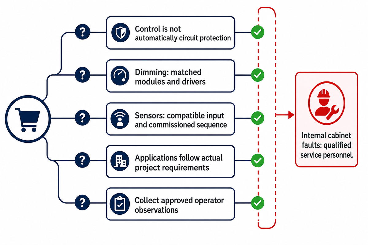
This information is intended to clarify typical purchasing and operating questions. The actual equipment schedule, driver interfaces and approved site procedures determine the installed system’s capabilities.
Is a Lighting Control Panel the Same as an Electrical Panel?
Control and protection have different documented roles.
A lighting control panel manages lighting operation; an electrical distribution panel supplies and protects circuits through its specified equipment. Some assemblies combine those functions, while others keep them separate. Read the actual panel schedule and protective-device requirements before assuming the control enclosure provides both. The name alone can’t prove that breakers, a main disconnect or the required protective coordination are included in the proposed cabinet.
Can a Lighting Control Panel Control Dimming?
Dimming requires a matched interface and driver.
A panel can control dimming when its installed modules and connected drivers support the required interface. A relay-only output provides switching. DALI, DMX and analog 0–10 V need their own compatibility and capacity checks. Specify minimum output, complete off and any required scene or diagnostic functions, then witness the light response. A dimmer command displayed on a screen doesn’t by itself prove the measured output at a luminaire.
Can Lighting Control Panels Work With Occupancy Sensors?
Compatible inputs and a commissioned sequence are required.
Lighting control panels can use occupancy sensors when the sensor output, controller input and programmed sequence are compatible. Detection coverage, placement, timeout and manual override need commissioning, rather than merely connecting the sensor. Define whether the project calls for automatic-on occupancy operation or manual-on vacancy operation, and check the approved sequence with the actual room layout. Where a sensor supplies information to other building systems, separately confirm the gateway mapping and what happens if communication is unavailable.
Where Are Lighting Control Panels Used?
Applications range from building zones to architectural systems.
Examples to assess include panels for offices, warehouses, schools and large commercial facilities, as well as suitable architectural and exterior lighting applications. Residential smart lighting can use controllers chosen for the project; a centralized panel should follow the actual project requirements.
Why Is My Lighting Control Panel Not Working?
Separate an operational symptom from an electrical fault.
A lighting control problem can originate in the supply/protection arrangement, a relay or dimming interface, the controller sequence, a network connection or a conflicting override. Collect observations using the approved operator controls: which zones are affected, the command shown, any visible alarm, the schedule and whether an authorized local control behaves as expected. Compare those observations with the approved operating instructions. Record when the issue started and whether it followed a configuration change or power restoration.
Qualified service personnel should investigate electrical or internal cabinet faults. Don’t open an energized enclosure, bypass protection or force an emergency circuit to test a theory. A gateway reporting an accepted command can still coexist with a driver, mapping or control-authority problem. The circuit-to-control record and saved configuration give the responsible technician a more useful starting point than repeated resets without a recorded symptom.
Evidence and scope: This guide combines public authority guidance and explicitly attributed manufacturer information with editorial procurement templates. Scenarios are generic. Sample procurement documents don’t supplant applicable electrical design, local requirements and/or manufacturer instructions. No third-party test, certification, patent or project saving is claimed as Guangqi Lighting’s own.
References & Sources
- OSHA: 29 CFR 1910.303, electrical equipment and protective coordination.
- DALI Alliance: addressing, control and querying features.
- ESTA: current published control-protocol standards.
- Lutron: 0–10 V compatibility, source/sink and electronic-off limitations.
- BACnet Committee: Protocol Implementation Conformance Statement.
- DOE/PNNL: Selecting Lighting Control Systems.
- DOE Better Buildings: St Paul lighting/HVAC integration case.
- NIST: building-system cybersecurity scope and lifecycle responsibilities.
- DALI Alliance: self-contained emergency-lighting test distinctions.
- DOE: measured performance in the 23-streetlight 0–10 V study.
- Oak Ridge National Laboratory: BACnet command priority and release behavior in its driver implementation.
Related reading: LED driver supplier selection helps develop the exact driver shortlist before the control-panel compatibility review.