Get in Touch with GUANGQI


Remote-Control Light Switch: RF, Wi-Fi, Relay Load, Range, and Commercial Limitations

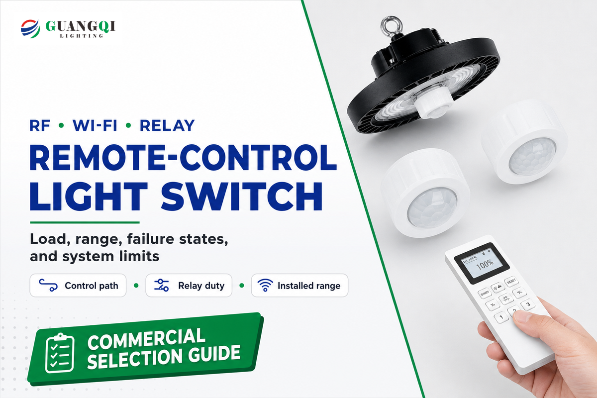
A remote control light switch is a user interface that sends a command to a load-switching device. That simple definition hides the engineering decision. An in-wall switch, receiver module, plug-in unit, or powered fixture still switches the electrical load. “RF,” “wireless,” or “Wi-Fi” identifies a command path; it does not prove compatibility with an LED driver, starting current, walls, metal enclosures, or a commercial operating sequence.
Approve the whole control path, not the remote in isolation. This applies to plug-in receivers, in-wall light switches, and wire-free keypads paired with another load-control device. Identify the load-carrying device, verify its voltage and load table, qualify the installed radio path, define failure behavior, and confirm installation and lifecycle requirements. If a project needs coordinated zones, sensors, schedules, emergency behavior, commissioning, or records, a stand-alone receiver may be the wrong system boundary.
Market boundary: the regulatory examples below are United States references, not global approval. For another market, verify the local electrical code, radio authorization, equipment certification, adopted energy requirements, and installer authority. Metric range equivalents are approximate conversions of the cited manufacturers’ imperial figures, not separate test results.
Key takeaway
RF or Wi-Fi does not determine load capacity. Use the exact receiver’s voltage and load-type ratings, test the real installation path, document local fallback and recovery, and escalate when the job needs coordinated commercial controls.
1. What a Remote-Control Light Switch Actually Contains
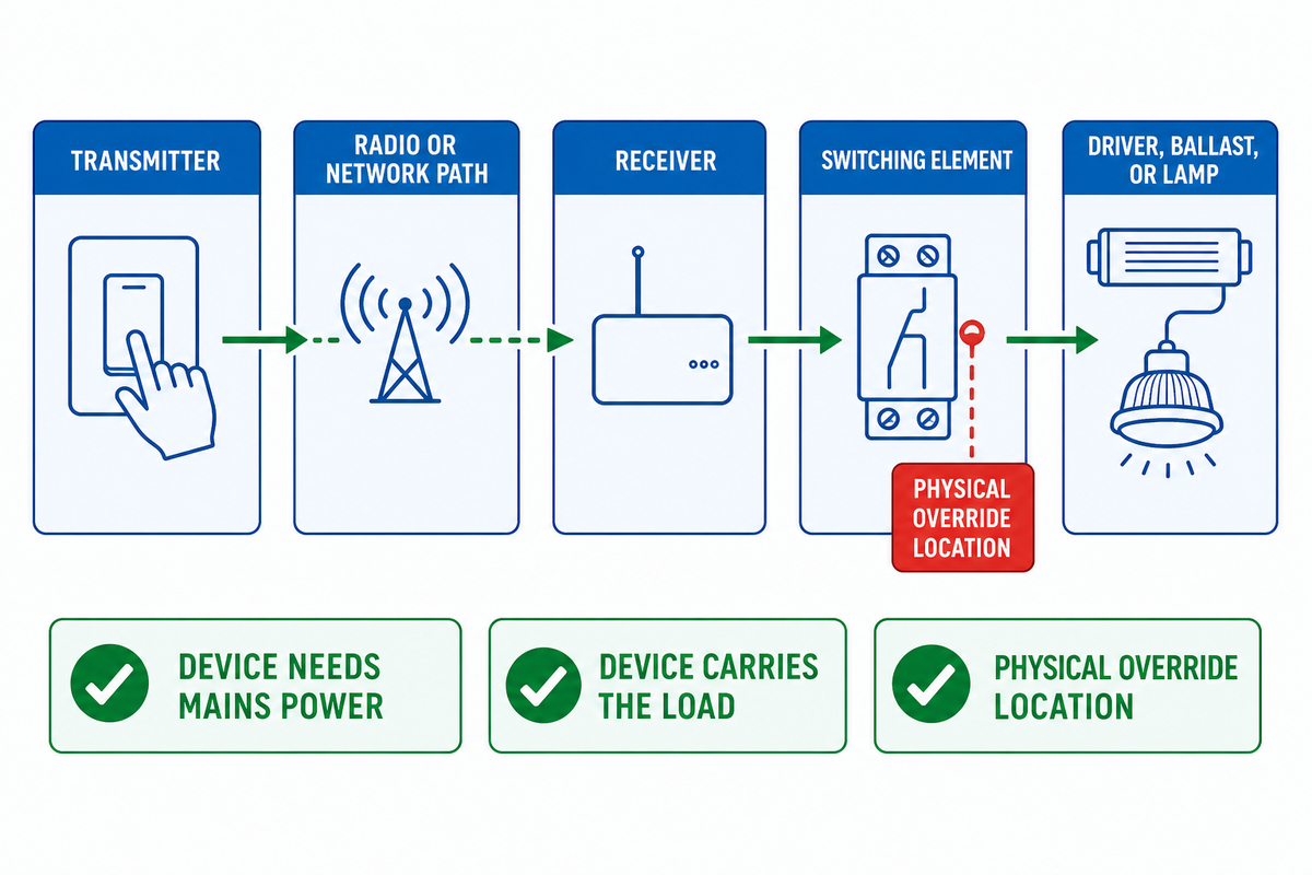
In many products, the visible “switch” does not switch the load. In a common wireless arrangement, the wall-mounted or handheld remote is the transmitter. It may be battery powered, self-powered, or wired only for its own electronics. Elsewhere, a receiver listens for the command, and its relay or electronic switching element opens and closes the load circuit.
Relays have a control side and a switched-contact side. Low-power control signals can operate contacts that carry a lighting circuit. This separation is why a long-distance remote can say nothing about allowable voltage, LED power, ballast capacity, motor load or contact life.
Three product topologies are especially common:
- Plug-in receiver: a lamp or cord-connected load plugs into the receiver, which plugs into an outlet. It avoids modifying a wall-switch circuit, but the outlet receiver still has a defined voltage, load type, and environmental rating.
- In-wall receiver or smart switch: the load-carrying device is installed in an electrical box. Neutral, grounding, conductor space, topology, listing instructions, and local rules remain relevant.
- Wire-free keypad plus powered receiver: the keypad can be placed on a wall without load wiring, but it controls a powered receiver elsewhere. “Wire-free” applies to the command device, not the load circuit.
Misassigned topology creates a direct specification risk because range, load, and power evidence can be attached to the wrong component. Before comparing brands, draw one line from the user command to the light: transmitter, radio or network path, receiver, switching element, and driver, ballast, or lamp. Mark which device needs mains power, which one carries the load, and where a physical override exists. This one-minute check prevents later design errors.
2. RF vs Wi-Fi: Compare the Control Path, Not the Label
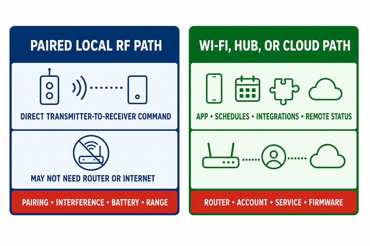
“RF” is a broad description: Wi-Fi is itself radio-frequency communication. In product comparisons, however, RF remote switch usually means a transmitter paired directly to a receiver on a manufacturer-selected radio protocol. A Wi-Fi light switch commonly joins a local network and may also use an app, user account, voice service, hub, or cloud platform.
Paired local RF path
- Can provide a direct transmitter-to-receiver command
- May not need a router or internet service
- Still has pairing, interference, battery, and range limits
- Features and security model remain product-specific
Wi-Fi, hub, or cloud path
- May add app access, schedules, integrations, or remote status
- Can create router, account, service, and firmware dependencies
- May retain physical or local control during internet loss
- Needs ownership and update planning over its service life
Not every smart switch stops working when the internet fails. Lutron, for example, documents that named Caseta devices use its Clear Connect path for in-home communication rather than Wi-Fi. That is a useful counterexample, not a category promise. App functions, remote access, automation, hub-power behavior, and another brand’s architecture can differ.
Connectivity also creates a lifecycle question. Finalized in April 2026, NISTIR 8259 Revision 1 says manufacturers can improve product securability by providing cybersecurity functionality and the information customers need. This article derives a procurement check from that manufacturer-focused guidance: for a connected switch, ask who owns the account, how access is removed when staff change, whether updates are available, how vulnerabilities are handled, what happens if a service is retired, and whether the device can be replaced without losing essential lighting control.
Retail Search Labels Are Not Specifications
Retail vocabulary can help buyers discover a product form, but it cannot replace a model-specific submittal. Read the following phrases as search labels only; never infer load, wiring, range, listing, or service compatibility from the wording.
| Label cluster | Examples a listing may use | Evidence still required |
|---|---|---|
| Product form | switch kit; wireless switch; smart light switch; smart switch kit; wireless light switch and receiver; light switch and receiver kit | Identify the transmitter, receiver, switching element, and connected load |
| Connected interface | Alexa; Google Assistant; Google Home; voice control; app control; WiFi; smart switches; smart bulbs; smart dimmer; dimmer switch; smart home; “control your lights remotely” | Confirm local control, account ownership, network dependencies, support, and recovery by function |
| Installation or load | 3-way; single pole; ceiling lights; lighting fixture; bulb; indoor; outdoor lighting; home lighting; appliance; small appliance; adapter; outlet set | Verify exact circuit topology, enclosure, environment, load category, and instructions |
| Radio or rating | RF remote control; “range wireless”; long range; 5A | Request a named model, test basis, voltage-specific load table, and installed-path acceptance test |
Make this translation routine: use retail language to find candidates, then return to the evidence checks in this guide. For the boundary between a point device and a coordinated project, GQLAMP’s commercial control planning guide provides the next planning layer.
3. Relay Load: Why One Amp or Watt Number Is Not Enough
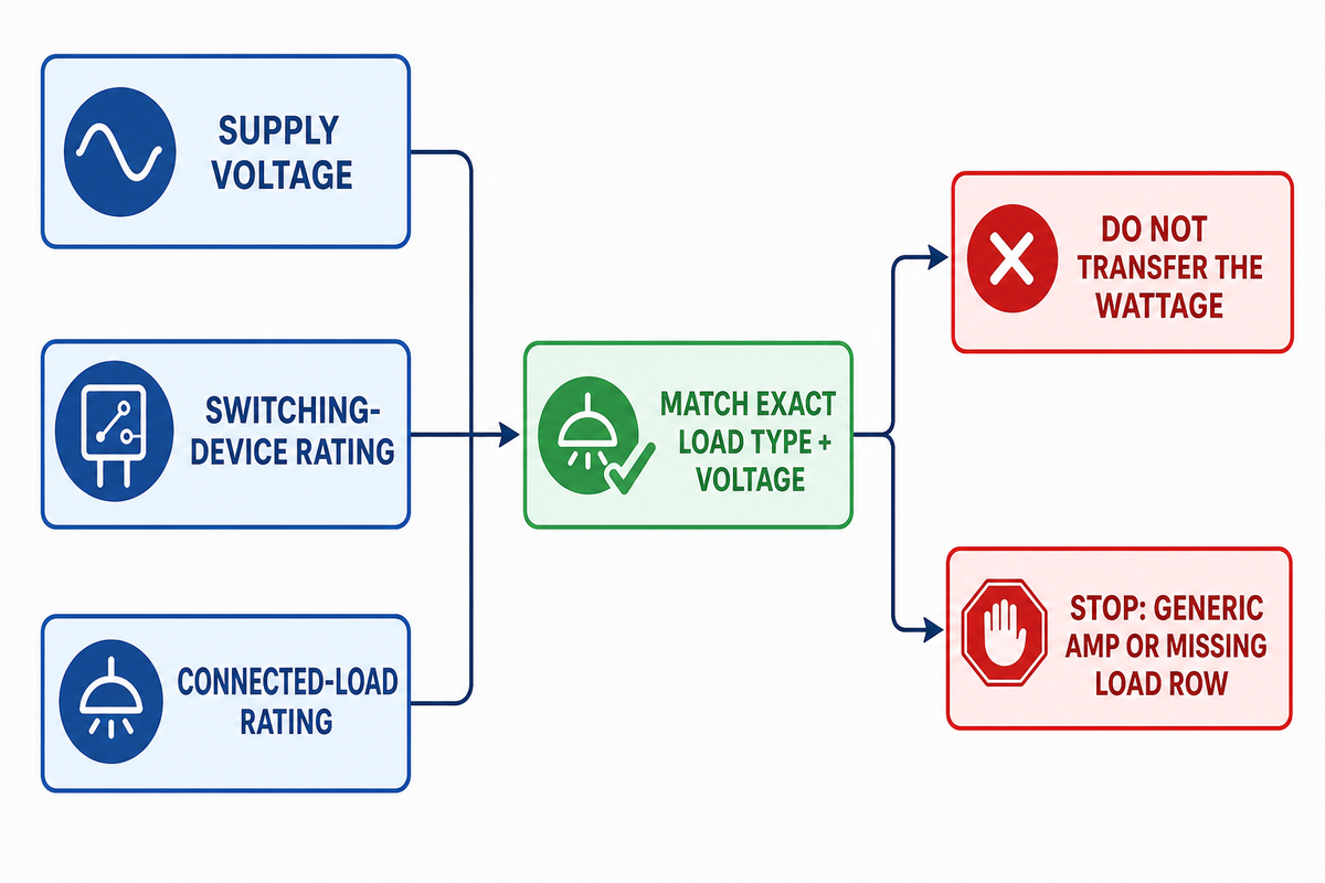
Start with three separate fields: supply voltage, switching-device rating, and connected-load rating. They are related but not interchangeable. Specifically, a 120 V receiver is not automatically acceptable on 230 V. Likewise, a general 5 A label does not automatically mean 5 A of LED drivers, fluorescent ballasts, motors, or every resistive load.
A relay contact rating is not one number: the operating problem includes closing surge, steady-state voltage and current, and the voltage developed when a load is interrupted.
LED drivers illustrate the issue. Their steady input current may be modest, while a short charging pulse appears at startup. Receiver contacts must close into that event. Motors and magnetic ballasts add different inductive behavior, while a resistor or incandescent filament behaves differently again. No universal derating percentage can replace the receiver manufacturer’s exact table and the connected equipment data.
One undated manufacturer sheet, accessible during this review, shows the required evidence granularity without establishing current product availability. Leviton’s WSS20 data sheet lists 400 W LED, 800 W incandescent, 1,200 VA fluorescent, and 1/4 HP motor ratings at 120 V; it gives 2,700 VA fluorescent at 277 V and describes zero-cross/high-inrush behavior. Those historical source-sheet figures belong to that receiver family. They are not ratings for another remote switch, and a current submittal should replace them before procurement.
| Model | Specification type | Published value | Valid interpretation |
|---|---|---|---|
| Leviton WSS20 | Supply | 120/230/277 V AC | Model-family voltage options; verify the selected catalog number |
| Leviton WSS20 | LED load | 400 W at 120 V | Named LED row only |
| Leviton WSS20 | Incandescent load | 800 W at 120 V | Not transferable to LED drivers |
| Leviton WSS20 | Fluorescent load | 1,200 VA at 120 V | Named ballast row and voltage |
| Leviton WSS20 | Fluorescent load | 2,700 VA at 277 V | Different voltage-specific row |
| Leviton WSS20 | Motor load | 1/4 HP at 120 V | Named motor duty only |
| Leviton WSS20 | Radio range | 50–150 ft | Manufacturer model-family statement, not site acceptance |
| Leviton WSS20 | Pairing | Up to 20 transmitter IDs | Named receiver capacity |
| Lutron PD-5S-DV 5 A 2-Button RF Switch | Radio range | 30 ft through walls; 60 ft line of sight | Named Lutron product conditions only |
| Lutron PD-5S-DV 5 A 2-Button RF Switch | Pairing | Up to 10 transmitters | Named product capacity, separate from WSS20 |
More model-bound details reinforce the same rule. That undated WSS20 source sheet gives a 50/60 Hz supply frequency, identifies a 902 MHz product family, and specifies a 25 W minimum load for its non-neutral model; these are historical examples, not proof of a currently offered catalog item. Pico documentation for the cited remote uses a 3 V power source and a 431–437 MHz radio band. None of these values can be transferred to a different receiver or remote.
| Evidence field | What it proves | What it does not prove | Buyer action |
|---|---|---|---|
| Supply voltage | Receiver power compatibility | Load-type capacity | Match circuit and exact model |
| General current | Declared broad contact limit | LED, ballast, or motor acceptance | Find the load-specific row |
| Resistive/incandescent rating | Named resistive or filament load | Electronic-driver capacity | Do not transfer the wattage |
| LED/electronic rating | Named electronic lighting load | Every driver’s inrush profile | Compare total load and driver data |
| Fluorescent/ballast rating | Named ballast category at a voltage | LED or motor use | Keep VA and voltage attached |
| Motor horsepower | Named motor duty | Lighting driver acceptance | Use the exact motor row |
| Inrush statement | Manufacturer considered startup behavior | Compatibility with an unnamed driver bank | Request limits or compatibility evidence |
| Minimum load | Lowest supported connected load | Flicker-free performance in every circuit | Check no-neutral variants carefully |
| Dimming role | On/off or modulation function | Protocol or driver compatibility | Do not use an on/off relay as a dimmer |
| Temperature/environment | Declared operating location | Wet-location or enclosure approval unless stated | Match the installation environment |
Stop rule: do not approve a receiver when the intended load type or the voltage-specific rating is absent. “The total watts are below the headline number” is not enough.
4. Range: Line of Sight Is Not Through-Wall Performance
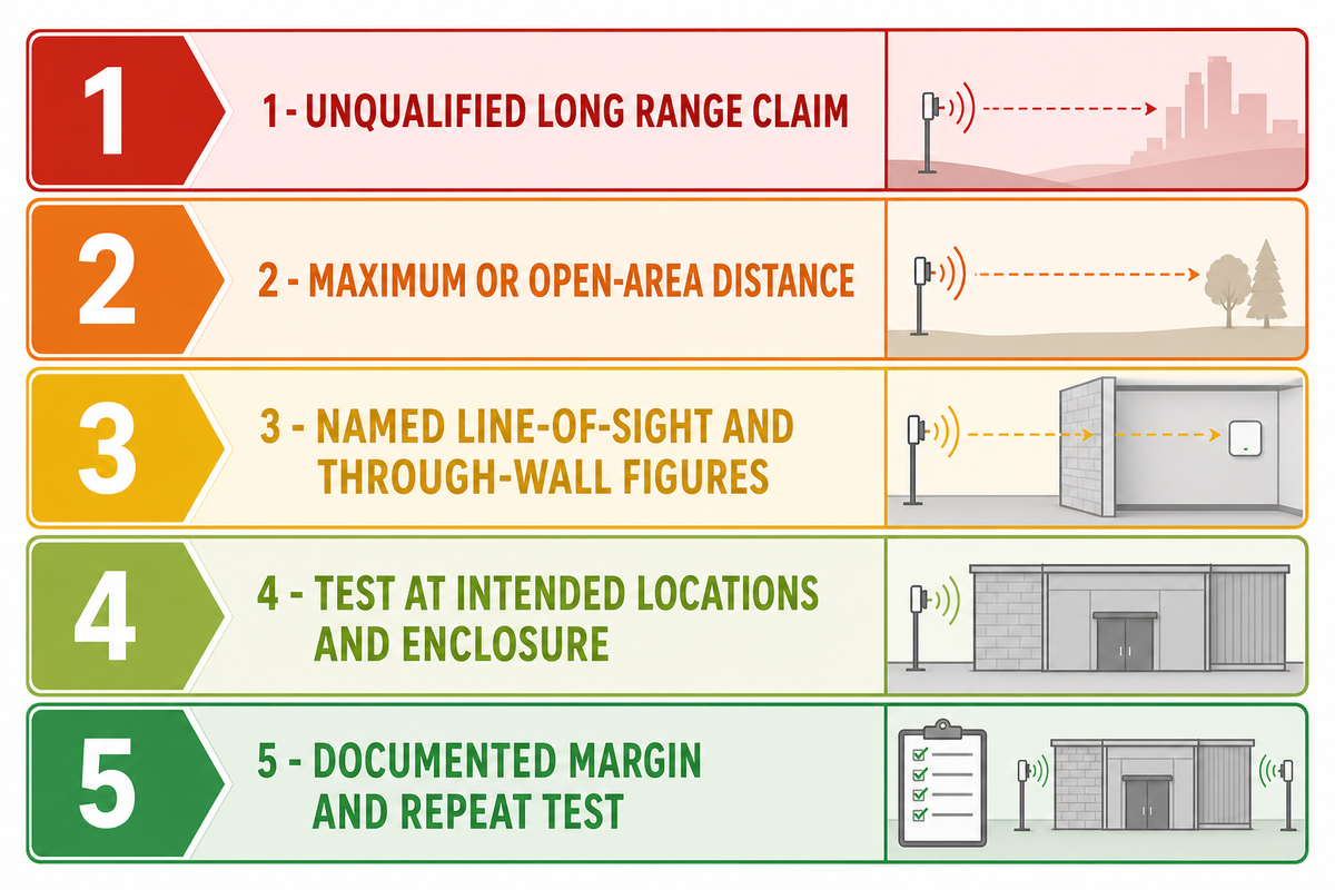
Published range is a screening input, not an installed acceptance result. Treating a marketing maximum as acceptance creates a reliability risk because walls, metal enclosures, equipment layout, interference, mounting position, and transmitter condition all change the radio path.
The Lutron PD-5S-DV 5 A 2-Button RF Switch specification publishes 60 ft (about 18 m) line of sight and 30 ft (about 9 m) through walls. The undated Leviton WSS20 sheet publishes a different 50–150 ft (about 15–46 m) range for its receiver family. These numbers are useful precisely because they are not interchangeable: each belongs to a model, radio design, and test statement, and the historical WSS20 figure still requires a current submittal before procurement.
In the United States, 47 CFR 15.5 requires Part 15 devices not to cause harmful interference and to accept interference. That legal operating condition is not a promise that a signal will cross a concrete wall, ignore a metal enclosure, or remain available at the edge of a marketing distance.
| Level | Evidence | Valid use | Remaining uncertainty |
|---|---|---|---|
| 1 | Unqualified “long range” claim | Discovery only | Nearly everything |
| 2 | Maximum or open-area distance | Initial shortlist | Building attenuation |
| 3 | Named line-of-sight and through-wall figures | Model comparison | Actual path and interference |
| 4 | Test at intended locations and enclosure | Site acceptance evidence | Long-term environmental change |
| 5 | Documented margin and repeat test | Maintainable acceptance | Future layout and equipment changes |
Test with doors, covers, panels, and equipment in their normal state. Use the weakest intended location, not only the best one. If the design depends on a repeater, hub, or mesh path, include that device and its power source in the written acceptance record.
5. Wiring, Listing, Grounding, and Installation Boundaries
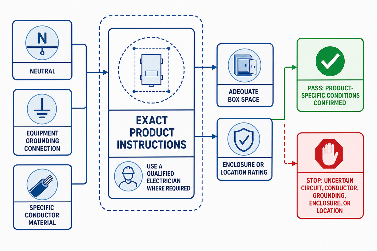
Wireless commands do not remove mains-wiring constraints. An in-wall receiver may require a neutral, equipment grounding connection, a particular line/load arrangement, minimum connected load, adequate box space, suitable faceplate, specific conductor material, and an enclosure or location rating. Circuit-to-product mismatch is the risk, not the absence of a radio link. No-neutral products use product-specific circuit designs; they do not create permission to ignore instructions.
For covered United States workplaces, OSHA requires listed or labeled equipment to be installed and used according to the instructions associated with that listing or labeling. Its wiring rules also address grounding, switch faceplates, boxes, and weatherproof enclosures in wet locations. These workplace rules do not replace residential requirements or the locally adopted electrical code, but they demonstrate why “it fits in the box” is not an installation approval.
Safety boundary
This guide does not provide a universal wiring procedure. De-energization, conductor identification, terminals, grounding, protection, and verification depend on the circuit, product, jurisdiction, and work setting. Use the exact instructions and a qualified electrician where required whenever the circuit, conductor material, grounding path, enclosure, or location rating is uncertain.
6. Failure State: What Happens When Control Disappears?
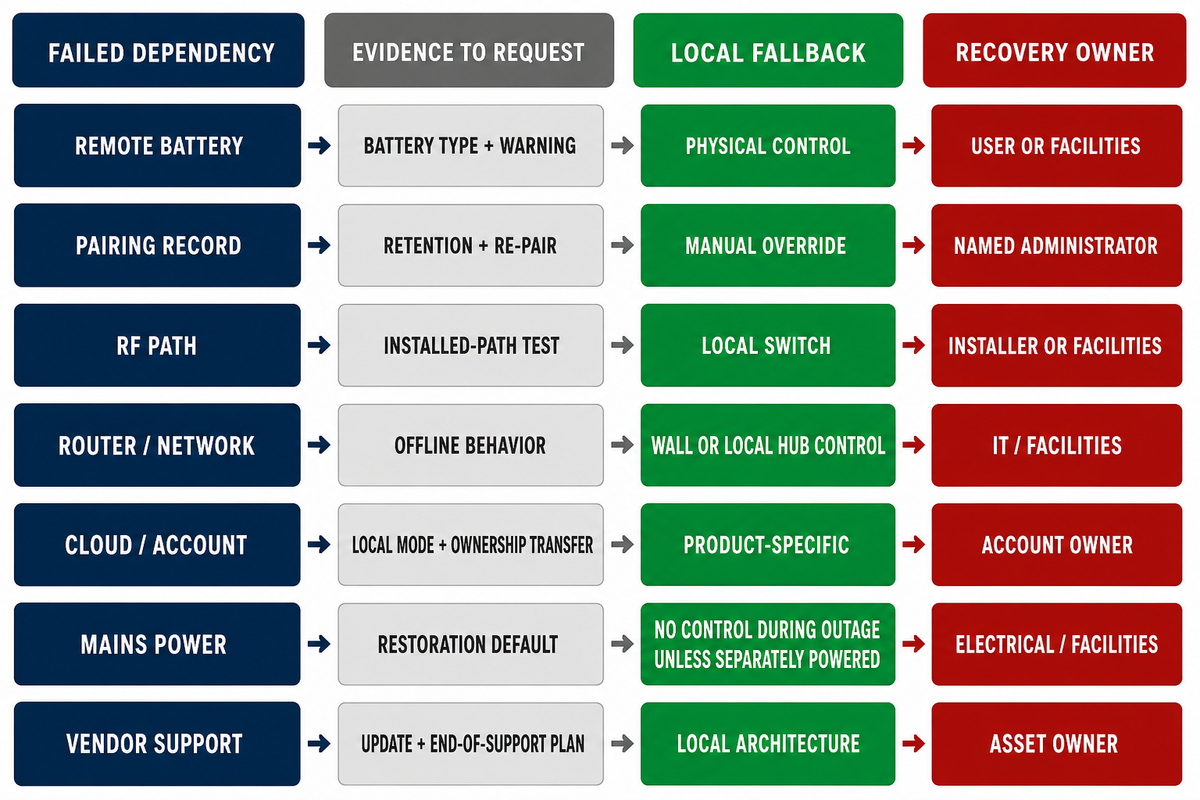
Normal operation is only one state. Define what remains available when a transmitter battery is empty, pairing is lost, radio noise rises, Wi-Fi fails, the router loses power, a hub stops, a cloud service is unavailable, the account is inaccessible, or mains power returns after an outage. The same model can fail differently by function; manufacturer lifecycle support is a separate dependency.
| Failed dependency | Evidence to request | Local fallback | Recovery owner |
|---|---|---|---|
| Remote battery | Battery type and warning | Physical control at receiver | User or facilities |
| Pairing record | Retention and re-pair procedure | Manual override | Named administrator |
| RF path | Installed-path test | Local switch | Installer or facilities |
| Router/network | Offline behavior by function | Wall or local hub control | Information technology/facilities |
| Cloud/account | Local mode and ownership transfer | Product-specific | Account owner |
| Mains power | Default state after restoration | None during outage unless separately powered | Electrical/facilities |
| Vendor support | Update, end-of-support, replacement plan | Depends on local architecture | Asset owner |
Record outcomes by function. A wall button may still work while remote app access, voice control, schedules, or status feedback fail. “The switch works offline” is too broad unless the statement names exactly which functions and dependencies were tested.
7. Multiple Switches, Multiple Loads, and the Management Problem
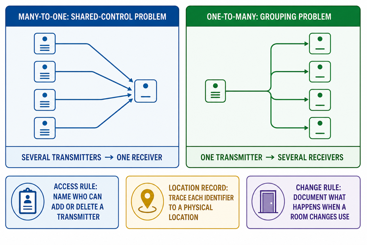
Many-to-one and one-to-many control are different. Several transmitters paired to one receiver create a shared-control problem. One transmitter paired to several receivers creates a grouping problem. Neither arrangement automatically provides documented zones, synchronized response, schedules, sensor logic, central status, or emergency behavior.
Verify the receiver’s pairing capacity and whether an identifier can be traced to a physical location. The Lutron PD-5S-DV 5 A 2-Button RF Switch supports up to 10 transmitters; the undated Leviton WSS20 sheet identifies a different capacity of up to 20 transmitter IDs. These are separate model examples, not a combined category range or proof of current availability.
As the count grows, maintenance and support become limiting factors. Procurement records should name who can add or delete a transmitter, how an unintended group command is prevented, how a failed receiver is identified, and what happens when a room changes use. If the answer is an undocumented sequence of button presses known by one installer, the arrangement is no longer easy to operate, even if every relay still responds.
8. When a Stand-Alone Relay Becomes a System Problem
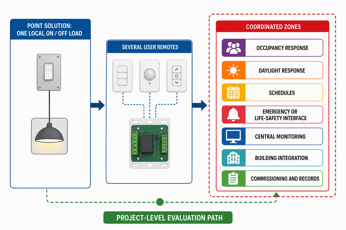
A stand-alone remote relay is a point solution. When one identified command operates one compatible load and the failure state is acceptable, it may fit. It is no longer a project-level control solution when the job demands repeatable coordination, required operating logic, maintained configuration, or evidence that required functions are present.
Official analysis of the 2018 International Energy Conservation Code shows that covered commercial applications can include automatic and occupancy-control functions. Locally adopted code, amendments, the authority having jurisdiction, and project documents govern the actual job, not this article or the example edition.
Commercial review can also include control location, visible identification, indication, zone limits, response, occupancy or daylight functions, and space-specific exceptions. These are not universal requirements for every remote; they are reasons to verify the adopted standard and design intent instead of multiplying independent receivers.
| Operating need | Standalone receiver fit | Evidence required | Escalation trigger |
|---|---|---|---|
| One local on/off load | Potentially suitable | Exact load, range, override | Any missing rating |
| Several user remotes | Model-dependent | Pairing limit and ownership | Unmanaged access |
| Several coordinated zones | Usually limited | Addressing and repeatable scenes | Configuration must be maintained |
| Occupancy response | Not proven by remote control | Sensor logic, coverage, timing | Required automatic behavior |
| Daylight response | Not a basic relay function | Sensor, zones, setpoints, commissioning | Closed-loop control needed |
| Schedules | Possible on some connected models | Clock, ownership, offline behavior | Portfolio-wide consistency |
| Emergency or life-safety interface | Do not assume | Approved design and documented behavior | Safety function involved |
| Central monitoring | Usually insufficient | Status, alarms, diagnostics | Operations needs visibility |
| Building integration | Product-dependent | Supported interface and responsibility | Cross-system sequence required |
| Commissioning and records | Weak without formal process | Device list, settings, tests, handover | Evidence must survive staff changes |
When those triggers appear, evaluate project-level commercial lighting control systems rather than treat more stand-alone relay kits as an architecture.
9. The 5-Gate Remote Switch Approval Check
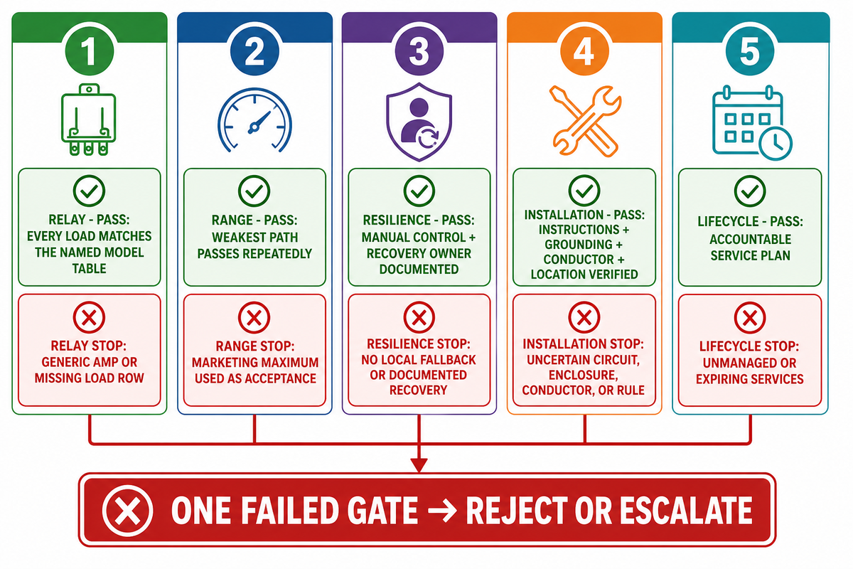
This editorial checklist turns the evidence into a purchase decision. It is not a certification, electrical design, or proprietary GQLAMP test. A model passes only when all five gates fit the same application, including the equipment-use boundary where that workplace rule applies.
| Gate | Required evidence | Pass condition | Stop condition |
|---|---|---|---|
| 1. Relay | Voltage, exact load type, inrush/driver evidence, switching role, environment | Every connected load is within the named model table | Generic amp or missing load row |
| 2. Range | Real path, barriers, enclosure, interference, acceptance test, margin | Weakest intended path passes repeatedly | Marketing maximum used as acceptance |
| 3. Resilience | Manual control, dependency map, retained pairing, restoration state, recovery owner | Essential control survives the accepted failures | No local fallback or undocumented recovery |
| 4. Installation | Listed/labeled instructions, grounding, terminals, conductor suitability, enclosure, location, protection | Exact product and installation are accepted by the responsible parties | Uncertain circuit, enclosure, conductor, or rule |
| 5. Lifecycle | Access control, updates, vulnerability handling, account ownership, support horizon, replacement path | Connected functions have an accountable service plan | Essential control depends on unmanaged or expiring services |
One failed gate is sufficient to reject or escalate the model. Failing Range but passing Relay produces an unreliable installation. Failing Installation but passing Range produces an unacceptable installation. If the first four pass and Lifecycle is ignored, you can leave a connected switch without maintained access, updates, or a replacement route. For a commercial project, also use the coordination trigger table before multiplying devices.
Planning a commercial lighting-control project?
Share the load schedule, circuit voltage, control locations, zones, sensing and schedule requirements, integration boundary, failure-state expectations, and commissioning needs. Include current drawings, required operating sequences, and the parties responsible for installation, testing, handover, and future configuration. GQLAMP can discuss the appropriate project-level control direction. State whether the request concerns one load, several coordinated spaces, occupancy or daylight response, central status, emergency interaction, or future building integration, because those needs change the system boundary and the evidence required.
10. Remote-Control Light Switch FAQ
Can I add a remote to an existing light switch?
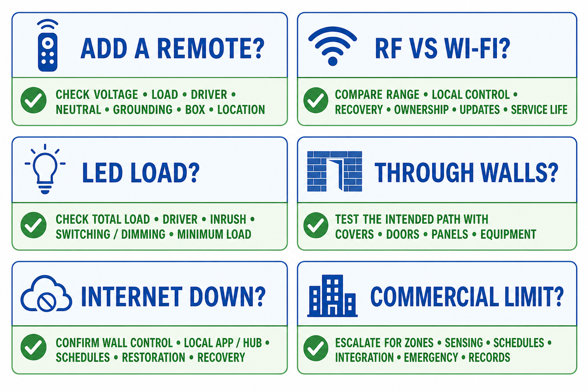
Often, but the method depends on the circuit and receiver. Verify voltage, load type, LED-driver rating, neutral and grounding requirements, box space, location rating, and the instructions. Ask a qualified electrician to confirm any uncertain circuit, conductor, enclosure, or grounding path.
Is RF better than Wi-Fi for a light switch?
Neither is universally better. Paired RF can provide local control without a router or cloud account. Wi-Fi may add app access, schedules, status, and integrations while adding network, software, account, and support dependencies. Compare installed-path range, local control, recovery, ownership, update policy, and service life.
Can a remote-control switch handle LED lights?
Remote-control switches can handle LEDs when the receiver is rated for that load and circuit voltage. Do not infer compatibility from incandescent, resistive, fluorescent, motor, or generic amp ratings. Check total load, driver type, inrush evidence, switching or dimming role, minimum load, and stated limits.
How far will a wireless light switch work through walls?
There is no universal through-wall distance. Manufacturers may publish separate figures for line of sight, ordinary walls, or open areas, and each number applies to a named product and test basis. Metal boxes, reinforced concrete, equipment, mounting position, interference, and transmitter condition can reduce performance. Use published range to screen models, then test the intended transmitter-to-receiver path with normal covers, doors, panels, and equipment in place. Keep margin instead of treating a maximum claim as acceptance.
Does a Wi-Fi light switch still work if the internet is down?
Sometimes. A physical wall control may continue working, and a product may support local-network or dedicated-RF control when internet service disappears. Cloud-only remote access, voice, automation, status, or account-dependent functions may stop. The answer depends on the architecture, not the Wi-Fi label. Confirm wall control, local app or hub operation, remote access, schedules, restoration state, and the documented recovery procedure for router, internet, hub, power, and service outages.
When is a remote light switch not enough for a commercial project?
A stand-alone receiver is too limited when the project needs coordinated zones, occupancy or daylight sensing, schedules, commissioning, integration, emergency behavior, diagnostics, access control, indication, or operating records. Adopted energy standards and project documents may also require functions the hardware cannot prove. Define those requirements before hardware selection. If repeatable coordination and maintained configuration matter, evaluate a project-level system.
References & Sources
- Electronic Code of Federal Regulations, 47 CFR 15.5
- U.S. Department of Energy, 2018 IECC Commercial Analysis
- OSHA, 29 CFR 1910.303 General Electrical Requirements
- OSHA, 29 CFR 1910.305 Wiring Methods and Equipment
- NIST, NISTIR 8259 Revision 1, Final April 2026
- ASHRAE/IES, Addendum bd to Standard 90.1-2022
- FDA, Electronic Relays Inspection Technical Guide
- Leviton, WSS20 Receiver Family Data Sheet
- Lutron, Caseta Clear Connect Support
- Lutron, Pico Remote Product Page
- Lutron, PD-5S-DV 5 A 2-Button RF Switch Specification
- IEEE, 802.11 Wireless LAN Standard Record