
Get in Touch with GUANGQI



A watts to amps calculator is a tool for estimating LED lighting running current from input power, voltage and power factor; it requires more information than what’s filled in on a lighting quote form. The electrical supply voltage, the true power factor, and the measurement boundary of the power rating determine the answer. Please enter the actual Alternating Current (AC) input watts to estimate the running current of the circuit; this result does not establish safe loading limits.
Watts to amps calculator: single-phase AC current is I=P/(VxPF). Balanced three-phase line current is I=Ptotal/(√3×VlinexPF). Use real input watts, RMS voltage and the appropriate true power factor. Results estimate running current.
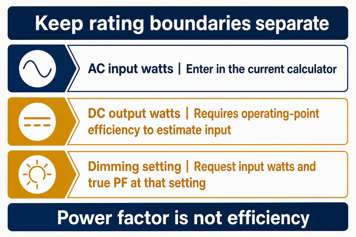
- The 120 W driver output rating is different from its AC input power. This doesn’t mean it draws 120 watts from the AC mains.
- In a balanced condition, the result is current in each line of the three phases; don’t add up three currents. Each line separately carries the calculated current for its phase.
- Setting a dimmer to 50% doesn’t establish 50% input watts.
- The amount of drivers each breaker can power, gauge of wire, and amp size are determined separately.
This publication is released by Guangqi Lighting for lighting design buyers and project teams. Manufacturer examples are identified by source, and load examples are illustrative calculations. They aren’t related to testing of Guangqi Lighting products. The references were verified in September 2026.
Single-Phase Watts to Amps Calculator
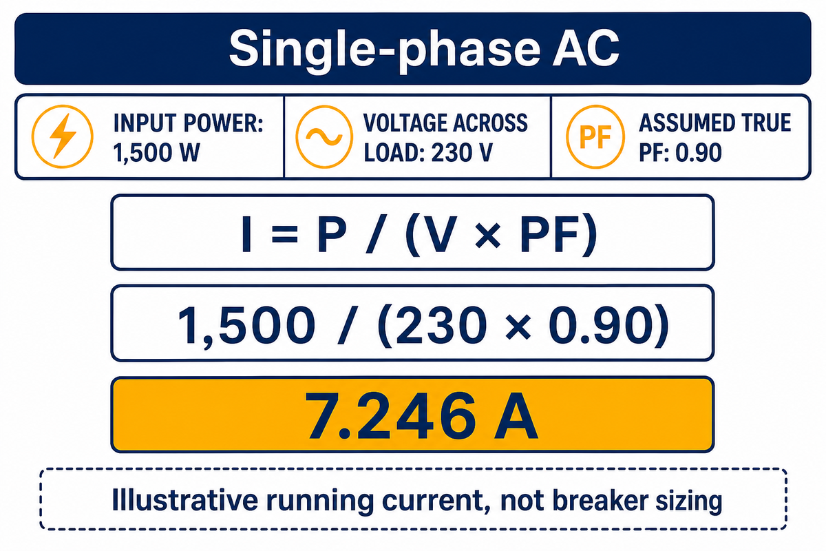
Single-phase alternating current is real input power divided by RMS voltage and true power factor. For converting watts, use the RMS voltage across the load. A 1,500 W bank at 230 V and PF 0.90 indicates a load current of approximately 7.246 A. PF 0.90 is used for example and can be changed based on the input.
Single-phase AC watts to amps
For a single-phase AC load, RMS input current I = real input power P / (RMS load voltage V times true power factor PF).
Estimated running current
A
Enter actual AC input watts and voltage across the load. Use the driver true power factor at the operating voltage and load. Running-current estimate only; not breaker, cable, neutral-current, inrush or installation sizing. Power factor is not driver efficiency.
Enter actual AC input watts and voltage across the load. Use the driver true power factor at the operating voltage and load. Running-current estimate only; not breaker, cable, neutral-current, inrush or installation sizing. Power factor is not driver efficiency.
Formula to convert watts: I [A] = Pinput [W] / (V [V] x PF). To convert watts to amps, enter all three values. Keep the assumptions with the electrical calculations. You can calculate amps, or amperage, only after identifying the input-power measurement boundary. True power factor is the ratio of True to Apparent Power. This definition considers the relationship of voltage and Current at a given operating condition. Efficiency on the other hand is the relationship of output and input Power. Using a typical power factor of a different driver is an assumption, even if this is entered as 0.9 in the calculator.
The University of Louisville AC lesson distinguishes volt-amperes from watts. Their sinusoidal power triangle is defined by phase angle. LED drivers can draw distorted current, so the assumption that displacement cos θ represents the complete power factor isn’t correct; true power factor is required for the conversion calculation. Fluke’s definition of power factor states the ratio of real power to apparent power.
How do you convert watts to amps?
- Choose the AC input rating, not LED output watts or an equivalent incandescent wattage.
- Convert kilowatts to watts first: 1.5 kW becomes 1,500 W.
- Enter RMS supply voltage and PF as a decimal, such as 0.90.
- Keep the resulting current with its input assumptions on the project schedule.
Someone who wants to quickly convert a “1,500 W lighting package” must first establish what that package includes. If 1,500 W means complete AC input, no efficiency correction is needed. If it means total DC power output, input losses remain unresolved. Ask the supplier which boundary the quote uses before treating 7.246 A as an offered-model value.
These interactive calculators cover AC systems. For steady direct current, use I=P/V with DC watts and voltage at matching measurement boundaries. AC and DC ratings can’t be interchanged. With AC, current changes direction over the cycle. The watts to amps conversion calculator reports an RMS magnitude. A solar panel, battery or Power-over-Ethernet supply needs its own operating-point and loss information; DOE’s PoE research explains why architecture and cable losses matter.
For a 1,500 W single-phase load at 230 V, changing the assumed PF from 1.00 to 0.90 raises the estimate from 6.522 A to 7.246 A. That difference comes from apparent power. It doesn’t mean the light produces more output or that the driver is only 90% efficient.
Three-Phase Watts to Amps Calculator
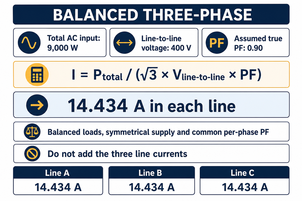
Total input watts across all phases and RMS line-to-line voltages must be found to determine the parameters of a balanced three-phase system. The calculation assumes approximately sinusoidal, symmetrical supply voltage and a common per-phase true power factor. With 9,000 W total, 400 V line-to-line and PF 0.90, estimated running current draw is 14.434 A in each line.
Balanced three-phase AC watts to line amps
For a balanced three-phase AC load, RMS line current I = total real input power across all three phases / (sqrt(3) times RMS line-to-line voltage times true power factor).
Estimated running current per line
A
Total watts must cover all three phases. Voltage is RMS line-to-line, not line-to-neutral. Balanced phase loading, approximately sinusoidal symmetrical supply voltages and a common per-phase true power factor are assumed. Do not substitute an aggregate effective three-phase power-factor definition. Result is RMS line current, not a sum of currents. Not suitable for unbalanced loads, neutral-current prediction, harmonic analysis or protective-device sizing.
Total watts must cover all three phases. Voltage is RMS line-to-line, not line-to-neutral. Balanced phase loading, approximately sinusoidal symmetrical supply voltages and a common per-phase true power factor are assumed. Do not substitute an aggregate effective three-phase power-factor definition. Result is RMS line current, not a sum of currents. Not suitable for unbalanced loads, neutral-current prediction, harmonic analysis or protective-device sizing.
Three-phase amps formula: Iline = Ptotal ÷ (√3 × Vline-to-line × PF). The square-root factor follows the phase relationship; it isn’t a safety allowance. The University of Louisville three-phase lesson explicitly limits this relationship to balanced loading and RMS quantities.
Consider an illustrative warehouse with three equal 3,000 W lighting banks, each having the same input PF. Their combined power is 9,000 W. On an ideal 400 V wye supply, line-to-neutral voltage is 400/√3, approximately 230.94 V. Calculating each bank separately gives 3,000/(230.94×0.90), about 14.43 A. The total-power method gives the same result. Entering 3,000 W as the total would understate each line’s current by a factor of three. Entering 230 V in the line-to-line field would describe a different supply. Make sure the phase schedule and voltage rating of the drivers support the requested lighting change.
Balanced loading doesn’t validate every harmonic-rich electrical system. NIST’s published LED measurement study shows that harmonic bandwidth and source impedance can affect measured active power. The calculator doesn’t analyze those waveforms. Nor should an aggregate “effective three-phase PF” with a different apparent-power definition be substituted for its per-phase PF input.
For three equal banks totaling 9,000 W at 400 V line-to-line and PF 0.90, 14.434 A is the line-current estimate. Buying three-phase distribution doesn’t make an individual 230 V driver a 400 V load. Driver connection voltage and feeder voltage belong in separate fields on the electrical schedule.
Read the LED Driver Label Before Entering Watts
A manufacturer nameplate or rating plate for LED drivers provides input information whose stated conditions need checking. For a given LED driver, you may find information regarding the maximum input current, various test conditions, and output conditions, but no actual input-watt measurement for the conditions at which the LED driver is dimmed. The listed information includes test conditions and typical values; separately listed values need not describe the same measurement.
For a concrete example, MEAN WELL’s HLG-120H specification, revision July 24, 2026, lists the following. The original PDF table, rather than an extracted text copy, is the source for these figures.
| Published item | Manufacturer value | How to use it |
|---|---|---|
| HLG-120H-48 rated output | 120 W | DC output, not the AC input field |
| HLG-120H-48 typical efficiency | 93.5% | An output-to-input relationship, not PF |
| Family AC current at 230 VAC | 0.6 A typical | Check the datasheet’s operating conditions |
| Family full-load PF at 230 VAC | ≥0.95 | A condition-specific typical value, not a dimming curve |
| Cold-start inrush at 230 VAC | 60 A typical; 375 µs at 50% peak | Switching information, separate from running current |
Source: MEAN WELL HLG-120H PDF, page 2; PF-versus-load curves on page 6. Single manufacturer source: these values are examples from that family, not specifications for Guangqi Lighting products.
If the stated efficiency is valid at that output, 120/0.935 = ~128.34 W of input would be needed; the estimate is conditional on those operating conditions. This value can’t be quoted as the input rating. For a quote, we need the input W and the RMS A at that voltage. Our LED driver input and output ratings guide explains these and other rating-related terms.
Dimming adds another unknown. PNNL’s 0–10 V streetlight study found inconsistent relationships between control voltage, input power and light output among the studied products. A “50%” command therefore doesn’t prove a 120 W input becomes 60 W. Request the offered model’s measured input-power and PF data at that setting.
A 120 W output label can’t, by itself, establish AC current. The HLG-120H example separates 93.5% typical efficiency, ≥0.95 full-load PF at 230 VAC and 0.6 A typical input current. Preserve each field’s conditions when comparing offers; multiplying unrelated nominal values creates precision the source doesn’t provide.
Watts vs Amps: Worked LED Lighting Examples
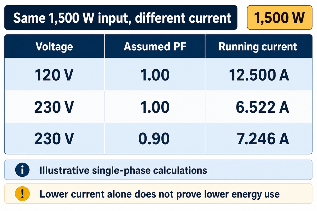
Real power is measured in watts. Power in watts measures the rate of energy transfer and, in single-phase AC, is equivalent to the product of voltage, amperage and true power factor. The difference in PF and voltage causes a difference in amperage. The same 1,500 W input can require different current at different voltage or PF. Therefore, amperage alone doesn’t indicate real power or establish lower energy consumption.
One watt, the unit of power, is defined as one joule of energy per second. The amp (ampere), by definition, is the unit of electric current, used to measure electric current flow in the international system of units; one ampere corresponds to one coulomb of electric charge per second. Potential difference (voltage) is often described as what pushes current through a circuit and is measured in volts (V). Neither amps nor voltage alone define real power; volts and amps cannot be converted into watts without the correct AC or DC relationship. These statements explain the relationship between watts and amps; they don’t allow interchangeable use of amps and watts.
| Supply voltage | Assumed true PF | Calculated running current | Buyer interpretation |
|---|---|---|---|
| 120 V | 1.00 | 12.500 A | Unity-PF reference value |
| 120 V | 0.95 | 13.158 A | Confirm offered-model PF |
| 120 V | 0.90 | 13.889 A | Default assumption is visible |
| 230 V | 1.00 | 6.522 A | Same input watts, lower current |
| 230 V | 0.95 | 6.865 A | PF still affects the answer |
| 230 V | 0.90 | 7.246 A | Primary calculator default example |
| 277 V | 1.00 | 5.415 A | Voltage-compatible driver required |
| 277 V | 0.95 | 5.700 A | No energy-saving claim implied |
| 277 V | 0.90 | 6.017 A | Still only a running-current estimate |
Calculated from I=P/(VxPF), with illustrative inputs and rounded to 0.001 A. No example is a driver rating or breaker allowance.
Suppose procurement compares two compatible drivers for the same 1,500 W input bank at 230 V. One has verified PF 0.95 at the required setting; the other’s quote assumes PF 0.90. The calculated difference is about 0.381 A. Finance can’t convert that difference into a kWh saving: both examples still use 1,500 W. The facility manager needs input-power measurements and operating hours to compare energy cost. Procurement needs equivalent light output and operating conditions before comparing purchase prices. Separately, choose floodlight wattage for the lighting task; electrical current doesn’t specify illumination.
For an amps to watts check, use the formula P=VxIxPF in single-phase AC circuits. At unity PF, 120V × 12.5 A gives 1,500 W. Ohm’s law, V=IR, adds resistance to a resistive circuit analysis; it doesn’t make every electronic driver a fixed resistor. Inductive or capacitive behavior changes phase relationships in sinusoidal circuits. The AC power equations explain why reactive power needs care when interpreting apparent power as useful work.
Unbalanced Lighting Loads Need Phase-by-Phase Checks
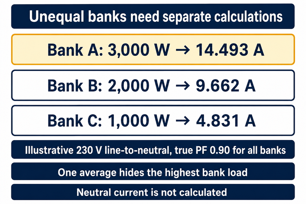
Loads of different character need not be balanced amongst all the phases of a 3-phase supply. To identify unbalanced loads and determine phase currents, individual phase currents need to be calculated from input watts, applied voltage and true PF for each single-phase bank. Total phase watts alone can’t determine individual phase currents or identify unbalanced loads in a 3-phase system.
Imagine three independently switched banks using 3,000 W, 2,000 W and 1,000 W. At an illustrative 230 V line-to-neutral and common PF 0.90, their calculated currents are 14.493 A, 9.662 A and 4.831 A. One average hides the first bank’s higher load. Turning one bank off also changes the pattern, even though the fixture model hasn’t changed. Before purchasing additional fixtures, the facility manager needs to supply the phase and switching schedule. Buying an equal number of fixtures for each phase is insufficient if wattages or operating schedules differ.
The balanced-system limitation is a mathematical constraint, not a lack of safety margin. The actual topology of the circuit influences the calculation when loads are connected line-to-line. The line-to-neutral schedule shouldn’t be reused without verification of connections. A voltage of 208 Volts between lines isn’t the voltage applied across a line-to-neutral driver on that supply.
“they summate in the N and they can result in N currents greater than those in the Line(Phase) conductors.”
Non-linear loads connected line-to-neutral may have neutral harmonics; line-to-line loads without a neutral require separate connection analysis. This conversion calculator does not produce a neutral-current or a wire-gauge result.
At 230 V and PF 0.90, illustrative banks of 3,000 W and 1,000 W draw about 14.493 A and 4.831 A respectively. Their unequal electrical loads can’t be replaced by the balanced feeder result. Keep the phase schedule and switching states with the estimate before approving additional lighting loads.
Why Running Amps Do Not Size the Breaker
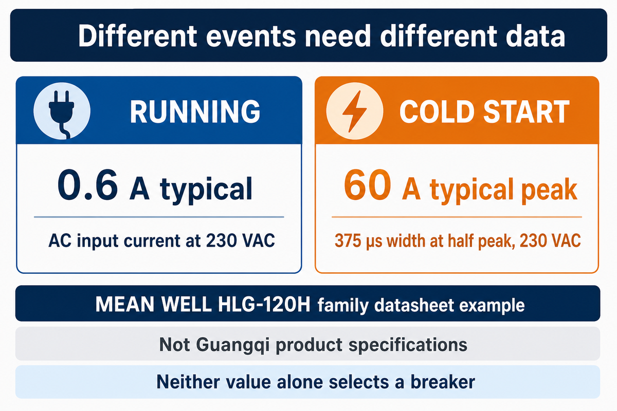
Running current describes steady state operation, while circuit breakers must also suit switching behavior and the installation. LED drivers may store energy at a rectified input and draw a rapid pulse of high input current at turn-on; the applicable line-to-line or line-to-neutral voltage is an input condition. During simultaneous driver switching, peak magnitude and pulse width affect protection and the allowable number of drivers on a circuit.
MEAN WELL’s example separates 0.6 A typical AC input current at 230 VAC from a 60 A typical cold-start peak, with 375 µs width at half peak. Those numbers describe different events. They don’t justify multiplying every driver’s running current by 100 or assigning a universal breaker curve.
Low running current can coexist with unwanted trips, so the root cause still needs to be identified. ADLT’s discussion on LEDs says that the impedance in the line and the driver impact the start-up behavior of parallel components. It isn’t necessary for 10 parallel drivers to have 10 times the peak and pulse duration of a single driver. Request the switching table of the protective device (and the controlled device) from the manufacturer.
Can I choose a circuit breaker from watts alone?
As explained in an article by IET’s Michael Peace, residual current protection devices respond to leakage; electrical engineering for circuit design also depends on other factors, including possible faults, installation conditions and local requirements. Residual-current protection introduces another issue: IET’s Michael Peace explains cumulative leakage from electronic power-supply filters . The article doesn’t endorse live testing of breakers or substituting them to stop a trip. Residual-current trips are not interchangeable with overcurrent events.
If a supplier offers a replacement driver with the same watts, ask whether its inrush and leakage currents remain within the approved switching-group limits; those matching watts do not establish final protection of the circuit. The supplier should provide driver data so the electrical engineer can evaluate switching group approval under the installed conditions.
Providing startup information is important when checking a circuit’s driver-loading constraints. A specification listing 0.6 A running current and a 60 A cold-start peak at 230 VAC illustrates why startup information belongs beside the load estimate. The manufacturer gives a 375 µs pulse width at half peak, with a 230 VAC supply, to describe that driver’s startup event. Neither the peak nor the running currents, alone, provide the circuit’s capacity.
What to Request in an LED Lighting Quote

Lighting quotes separate known inputs and assumptions from missing information. The 3-State LED Input-to-Quote Worksheet identifies the assumptions, decisions and parameters associated with each electrical field. An assumed PF can help in preliminary cost estimating; however, it shouldn’t be finalized as a verified product specification without supporting operating-point data.
3-State LED Input-to-Quote Worksheet
| Input category | Example entry and state | Evidence needed | Owner and decision |
|---|---|---|---|
| Supply voltage | 230 V assumed | Project electrical schedule | Facility manager: confirm location |
| Power boundary | AC input required; known method | Complete luminaire input rating | Procurement: reject output/input mixing |
| Bank input watts | 1,500 W assumed | Quantity × matched input W | Procurement: update with offered model |
| Operating PF | 0.90 assumed | PF at voltage and load | Supplier: replace the default |
| Driver identity | Missing | Model, revision and dated sheet | Procurement: lock substitutions |
| Dimming point | Missing | Input W and PF at setting | Facility manager: state operating schedule |
| Phase allocation | Missing | Bank-by-bank phase schedule | Designer: test balance assumption |
| Switching group | Missing | Count, peak, duration and compatibility | Designer: review startup constraint |
| Leakage and protection | Missing | Model-specific leakage evidence | Designer: review protective devices |
| Energy comparison | Missing | Input W × operating hours | Finance: compare kWh at equal light output |
The worksheet is an editorial procurement method. Its field separation follows the manufacturer’s distinct input, PF, efficiency and inrush specifications and the laboratory evidence on dimming. The populated figures are assumptions, not a completed site survey.
Using power data, the worksheet captures relevant information to evaluate quotes and identify knowledge gaps. Fields may be left open during procurement, but the electrical designer can see why quote approval remains pending. Finance should analyze comparable quotes and not automatically assume that a reduced amperage quote will result in a reduced power consumption.
For a Guangqi industrial LED lighting project, send the fixture list, project voltage and operating schedule with the worksheet. Include the requested driver model or ask for its supporting data. Review the available LED driver product families, then confirm the offered model’s electrical conditions before ordering.
What Is Changing in LED Driver Specifications
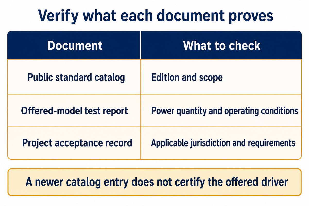
Electrical specifications should list the tested operating conditions and the edition of any referenced standards. Public standard catalogs change, and newer editions have been published since older driver guides were written. A more recent catalog entry doesn’t signify model certification or local adoption of the standard. Verification of model acceptance cannot be inferred from a catalog’s publication authority; check the applicable jurisdiction and the documentation provided.
The catalog for IEC 61000-3-2, consolidated edition 5.2 published on March 4, 2024, includes an interpretation sheet for 2025. Its public scope concerns harmonic current emissions from equipment within the standard’s stated input-current range. The listing of the standard does not provide a breaker-selection instruction for the equipment.
IEEE 1459-2025, published May 16, 2025, supersedes the 2010 edition and addresses power measurement under sinusoidal, nonsinusoidal, balanced and unbalanced conditions. Only the public catalog scope is cited here; the full paid standard hasn’t been reproduced. Ask which power quantities a supplied test report actually measures.
To obtain evidence of the new operating condition, request revised input power and power factor data while retaining the existing records. Measuring the full load at 230 V doesn’t answer part load questions at another voltage. Keep the unknowns in view until the revised proposal provides the answers.
Frequently Asked Questions
How many watts is 1 amp?
One amp has no fixed watt value; voltage and power factor determine single-phase AC power at the stated operating point, so the current rating alone is insufficient.
One amp doesn’t correspond to a fixed number of watts. For a single-phase AC load, multiply the current by the voltage and true power factor. At 230 volts and a power factor of 0.90, one amp corresponds to 207 watts of real input power. At unity power factor it corresponds to 230 watts. Those are calculated conditions, not universal LED driver ratings.
How many amps are needed to power 3000 watts at 240 volts?
A 3,000 W single-phase load at 240 V draws 12.5 A at unity PF or about 13.89 A at PF 0.90, using actual input watts at the stated operating point.
A 3000-watt single-phase load draws 12.5 amps at 240 volts if its power factor is one. At a power factor of 0.90, the calculated running current is about 13.89 amps. Use actual AC input watts and the load’s specified power factor. This answer doesn’t determine the breaker size, allowable fixture count or conductor selection for the installation.
How many amps to run 1000 watts?
A 1,000 W load at 120 V draws about 8.33 A at unity PF or 9.26 A at PF 0.90, provided those watts describe actual AC input power.
At 120 volts and unity power factor, 1000 watts corresponds to about 8.33 amps. With a power factor of 0.90, the same real input power requires about 9.26 amps. A different supply voltage changes both answers. Check whether the quoted watts describe the luminaire’s AC input or the driver’s DC output before entering a value into the calculator.
Is 1500 watts equal to 15 amps?
1,500 W equals 15 A only under matching voltage and PF conditions, so that equivalence cannot be used as a universal rule for an unspecified lighting supply.
For example, 100 V at unity PF gives 15 A. At 120 V and unity PF, the same 1,500 W gives 12.5 A.
Can this calculator check a 12 V LED strip?
Steady DC circuits use I=P/V, without an AC phase or PF correction; use matching DC measurement boundaries and check cable losses separately with the appropriate DC sizing tool.
Use DC input watts and voltage at matching measurement boundaries. Cable losses need a separate check; use the DC power sizing and voltage drop calculator.
Related Articles
- LED driver selection and rating guide
- LED flood light wattage guide
- Watts and kilowatts conversion guide
References & Sources
- University of Louisville: AC power and balanced three-phase power.
- MEAN WELL HLG-120H specifications, July 24, 2026 revision, pages 2 and 6.
- PNNL-32949: energy and operational impacts of 0–10 V control , 2023 report; public summary dated 2024.
- Martinsons, Zong, Miller and Ohno: LED power-measurement study , 2013.
- IET harmonics webinar Q&A, 2020; Michael Peace: Earth leakage, 2021.
- IEC 61000-3-2 official catalog and IEEE 1459-2025 official catalog, public metadata.
- DOE: Power-over-Ethernet technology; Fluke: power-factor definition; ADLT: LED inrush currents.