Get in Touch with GUANGQI



Updated October 2026
A description of street lighting design standards outlines the requirements for assessing a road lighting scheme, from visual task to calculation method, uniformity and glare. Work with the road owner’s project requirements and confirm the design against the specific luminaire being supplied. A wattage, pole height or average lux figure won’t definitely answer these questions.
There are six checks that connect a design brief to a usable submission. They cover governing documents, task classes, measured quantities, uniformity and glare, site geometry, and product-file identity. The following worked examples are for illustration only and aren’t design limits.
Which street lighting standards govern this project?
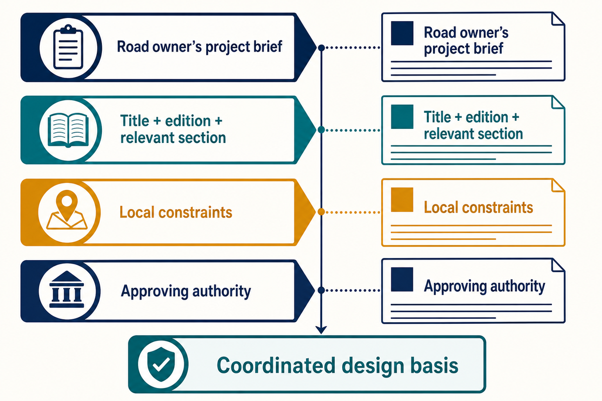
For a street lighting project, the road owner’s requirements and the applicable edition of the specified document, and the requirements of the locality need to be determined before selection of numerical criteria. A publisher’s latest edition identifies an available reference. The project brief must identify the reference to be used by the designer and where it applies and who accepts the resulting design.
The Illuminating Engineering Society lists ANSI/IES RP-8-25+E2 for roadways and parking facilities. CIE guidance addresses road lighting classes, while European and British documents use their own defined selection and performance methods. Similar terminology does not mean equivalent classification.
Local constraints need to be mentioned separately in the Brief. The FHWA lighting-system selection chapter notes that local codes can impact types of lighting systems, light trespass and skyglow. Request that the designer include those constraints alongside the project criteria that are being adopted. A supplier’s statement that a fixture “meets international standards” doesn’t identify a calculation method or an approving authority.
Always retain the title, edition and relevant section of a document together. If the brief names an older edition, clarify the difference with the owner before amending the basis of calculation. This stops Procurement comparing documents prepared to different instructions. With the scope defined, the LED street-light product range is a starting point for requesting model-specific files.
Assign road lighting classes to each visual task
Road lighting classes define a photometric requirement related to a visual task. They should be selected based on the character of the traffic on the various classes of roadways, pedestrian ways, and other areas of conflict, and the other roadway and surrounding conditions. Road width, alone, doesn’t allow determination of the road lighting class needed for a given location.
CIE 115:2010 describes the selection of M, C and P classes based on a visual task involving luminance and/or illuminance. Its public summary supports that distinction, rather than a universal schedule of lux values. The designer responsible for the class should provide justification to the client.
4-Field Road Class Record
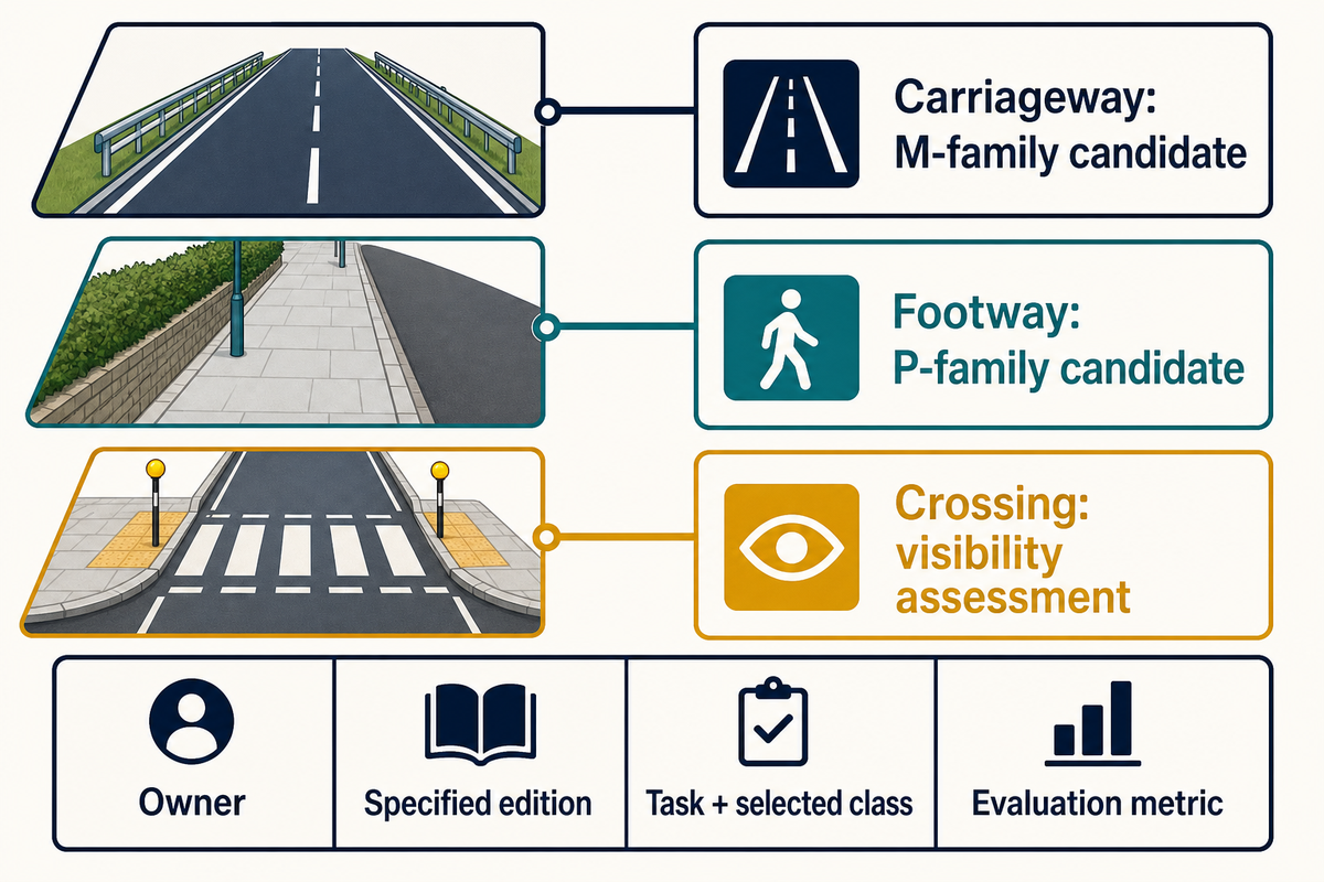
Put four fields on each marked area of the drawing: owner, specified edition, task and selected class, and evaluation metric. The filled example records an unresolved decision honestly, so a procurement engineer can see why the submission is held.
| Owner | Specified edition | Task and selected class | Metric and next action |
|---|---|---|---|
| Municipal road owner | Brief lists CIE 115:2010; local adoption unresolved | Main carriageway; M-family candidate, numbered class unassigned | Luminance method proposed; designer to submit class justification |
| Same owner; crossing reviewer identified | Crossing supplement not yet identified | Midblock pedestrian crossing; independent visibility assessment needed | Confirm pedestrian evaluation plane and approach directions before acceptance |
| Footway asset owner | Owner’s pedestrian-route criteria requested | Footway; P-family candidate, numbered class unassigned | Confirm illuminance criteria and grid; procurement hold remains |
Consider a hypothetical boulevard submission with a carriageway, footway and midblock crossing. The contractor gives one colored plan showing “road lighting” and asks the owner to approve the whole scheme. The document above shows three separate decisions. The designer first marks the areas and provides the proposed classification for each. The crossing reviewer, rather than checking the brightness of the paving, views the pedestrian from the approaching driver’s direction. Procurement maintains the luminaire order in a provisional state until these decisions are finalized. Although a bright rendering may help to illustrate the scheme for discussion, the owner now has specific questions to consider as opposed to having a single image to accept or reject.
FHWA’s crosswalk visibility guidance discusses avoiding the silhouette effect by making positive contrast between pedestrians and their background. Whether the pavement looks well-lit is a different question.
Read illuminance and road-surface luminance separately
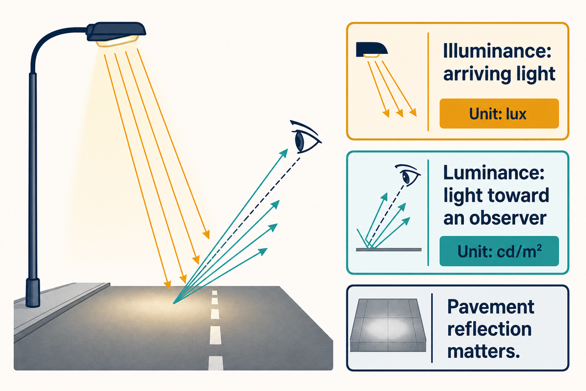
Luminance describes light leaving a surface toward an observer, expressed in candelas per square metre. Illuminance measures illumination arriving at a surface, expressed in lux. Reflection of a surface affects the view of the driver. Therefore, the design of a road report should state which of the two quantities it examines.
The review by Fotios and Gibbons on road lighting research addresses the relationship between reflection of the pavement, illuminance, and road surface luminance. Thus, a calculation using wrong assumptions for the pavement may misrepresent the case for a driver’s view, even if the luminaire file is correct.
| Report entry | Illustrative value | What to check |
|---|---|---|
| Horizontal illuminance | 12 lx | Surface, grid and maintained or initial state |
| Road-surface luminance | 0.6 cd/m² | Pavement model and observer geometry |
| Vertical illuminance | 8 lx | Plane height and direction facing the observer |
Those values are individual report entries, not a conversion table. If a vendor provides an illuminance screenshot in replacement of a luminance result, request that the specified calculation be reinstated. When determining pedestrian evaluation, also check which way the vertical plane is facing; a value on the opposite face of the plane can’t answer the same question regarding visibility.
For a quick error check, use units. A requirement written in cd/m² can’t be verified with a number labeled lx, without specifying the model and method. Evaluate the quantity before comparing suppliers, so that an attractive average light level doesn’t conceal a variation in what was calculated.
Check uniformity and glare without mixing metrics
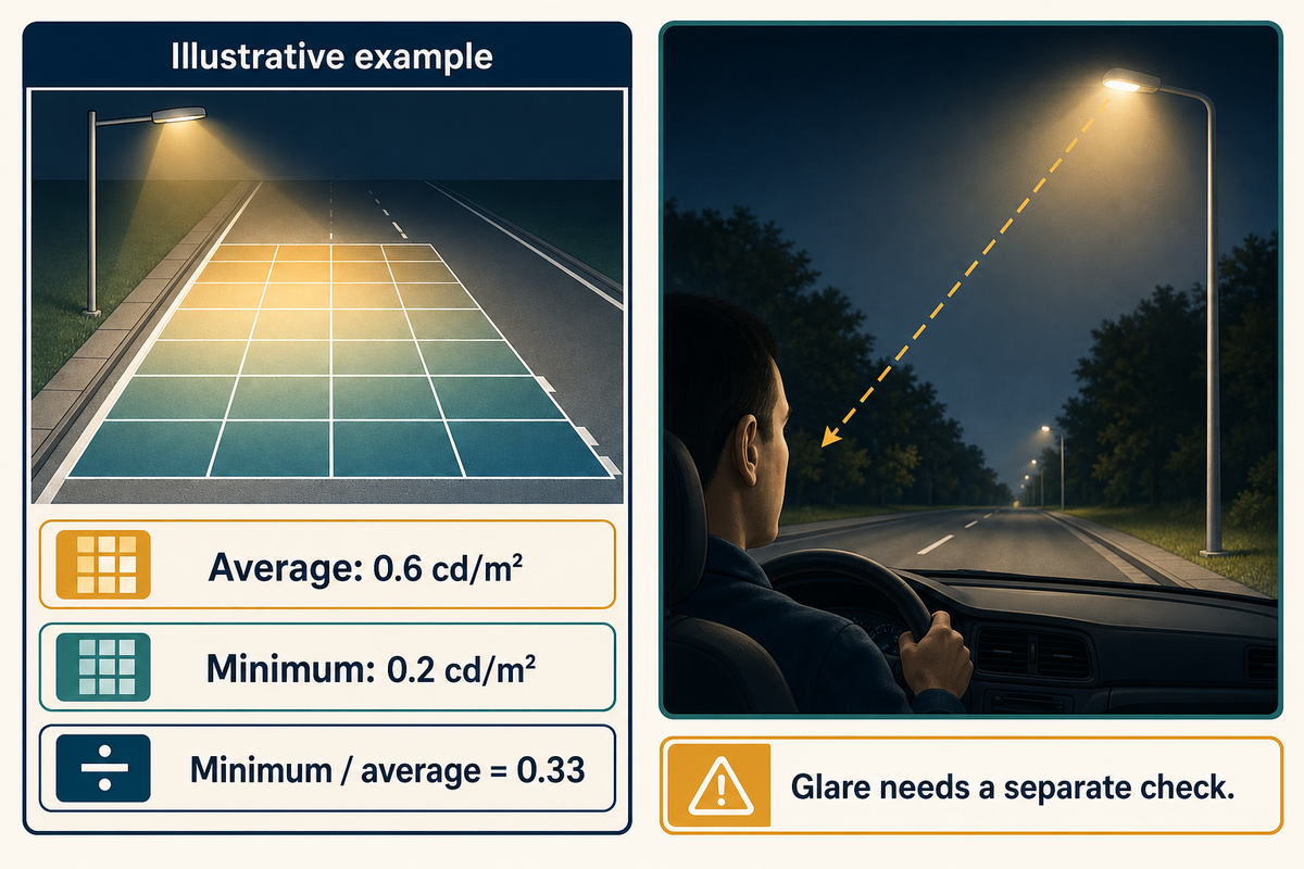
Uniformity describes variation across the specified evaluation area; glare describes a different visual effect. It isn’t appropriate to compare two reports if their metric definitions, grids and operating states don’t align. A good average may be masking a poorly lit point, and a uniform road surface doesn’t guarantee acceptable glare for approaching drivers.
The historical FHWA vision chapter explains how disability glare reduces contrast, and that’s the reason a review requires the applicable glare calculations and surface light levels. Product labels and an indoor glare rating won’t replace the evaluation of the roadway project.
Suppose an illustrative luminance grid has an average of 0.6 cd/m² and a minimum of 0.2 cd/m². The minimum-to-average ratio is 0.2 ÷ 0.6 = 0.33. State the ratio you’re going to compare before stating the limit.
Don’t rename a minimum-to-maximum illuminance ratio “longitudinal uniformity” without establishing the referenced method. The measured quantity, evaluation line or area, and the ratio convention are all important. Request the calculation output with the minimum point, and check that the method named by the Owner is used. There’s no need to create a universal uniformity limit to detect a ratio that’s mislabeled.
Do
- Read the full metric name beside every ratio.
- Check the grid and operating state.
- Request the separate roadway glare result.
Don’t
- Accept an average as a complete assessment.
- Swap illuminance and luminance ratios.
- Infer glare performance from a rendering.
Build the street light layout around actual geometry
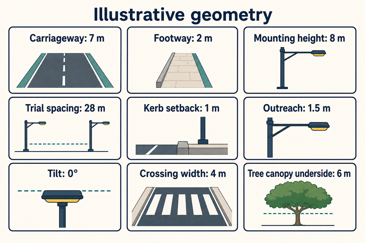
A street light layout requires a surveyed road cross-section, the height of the light source, optical distribution and relevant obstructions. Pole spacing is determined by testing the layout against the chosen criteria. A spacing-to-height relationship may suggest a layout, but it can’t consider all the constraints on site, like setbacks, crossings, curves and optics.
The input matrix below serves as a hypothetical survey-to-model check. Dimensions are included to illustrate how minor changes in design can affect the analysis. The final column indicates when a value can’t be transmitted to other parts of the roadway.
| Input type | Illustrative drawing | Buyer or designer action | Limitations / Not suitable for |
|---|---|---|---|
| Carriageway width | 7 m, two lanes | Match the calculation boundary to the surveyed kerbs | A widened 10 m junction needs its own geometry |
| Footway width | 2 m | Assign a separate pedestrian evaluation area | Does not include an adjoining 4 m plaza |
| Light-source mounting height | 8 m | Check the optical centre rather than pole catalogue length | Do not reuse a model calculated at 10 m |
| Longitudinal spacing | 28 m trial | Calculate the full bay with the proposed optic | No approval implied for a 35 m bay |
| Kerb setback | 1 m | Locate the light pole base and optical centre separately | A 2 m setback changes the cross-section |
| Outreach | 1.5 m | Confirm the bracket drawing and luminaire position | A 0.5 m arm is a different geometry |
| Tilt | 0° in the trial model | Match installation instructions and calculation orientation | A 5° field adjustment requires review |
| Crossing width | 4 m marked crossing | Check both approach directions and pedestrian visibility | The road-surface grid alone is insufficient |
| Tree canopy | 6 m illustrative underside | Record the obstruction and its position relative to light paths | A changing canopy is not a fixed optical assumption |
These are editorial review actions based on the geometry and placement issues discussed in FHWA’s historical roadway lighting review. They don’t include the earlier design criteria.
How far apart should lights be spaced?
Street lights should be spaced based on a photometric analysis using the chosen fixture, road geometry and project criteria. No single distance works for all mounting heights or distributions. In the hypothetical matrix, changing a trial bay from 28 m to 35 m alters the points that need to be illuminated. Keeping the same 8 m mounting height doesn’t keep the result the same. Have the designer check the revised minimum values, uniformity and glare, and then check the footway and crossing. Include a banner, and evaluate the effect of fully mature trees and other obstructions. Have procurement review the revised calculations and drawing. An unchanged wattage on the quotation isn’t evidence that a wider spacing produces the desired effect.
Match photometric files to the quoted luminaire
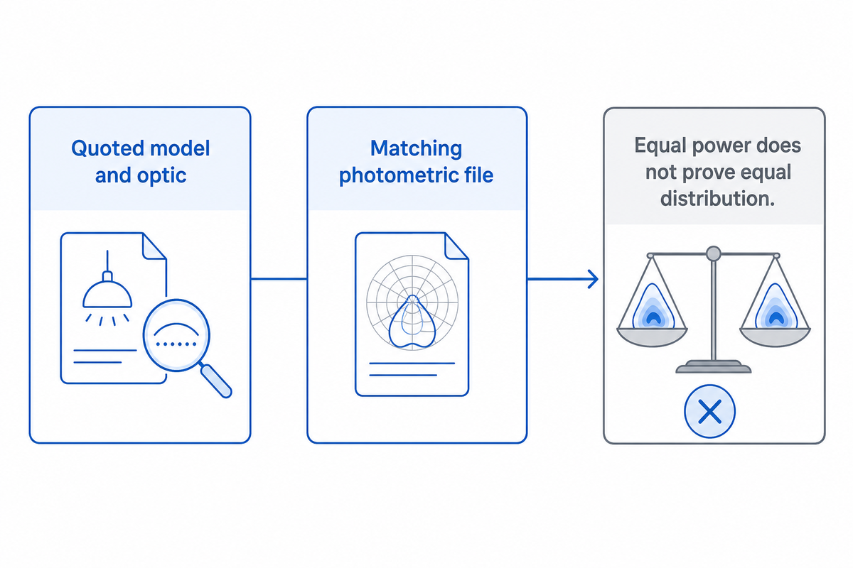
A photometric file should identify the luminaire and the operating setup of the lighting plan. Reviewers should also verify the optics and settings of the quoted model. The reviewer should review the assumptions for mounting and maintenance. A photometric file for a similar fixture can provide a persuasive result, but may describe equipment that the end user won’t receive.
“Comparisons should be based on photometric data provided by the supplier from an independent testing laboratory.”
Photometric File Match Sheet
Use the first six rows to identify the product and layout. The remaining rows capture the operating state and revision controls needed by the designer, quality reviewer and purchasing team. Every value below belongs to one hypothetical submission.
| Check | Filled example | Action on mismatch | Limitations / Not suitable for |
|---|---|---|---|
| Model identifier | Road-A on quote and file | Request exact file-to-model traceability | A family name alone is insufficient |
| Optic | Quote B; calculation A | Hold selection and recalculate with B | Matching wattage cannot resolve this difference |
| Output setting | 80 W quoted; 100 W file label | Clarify test and operating settings | Do not scale without a justified method |
| Tilt and orientation | 0° drawing; 5° model | Align model and installation instructions | Output totals do not describe directional changes |
| Mounting location | 8 m height; 1.5 m outreach | Compare the same optical-centre coordinates | Pole length is not necessarily mounting height |
| Maintenance basis | Factor 0.80 assumed; evidence missing | Request factor basis and maintenance schedule | No universal 0.80 recommendation is implied |
| Dimming state | 100% output model label | Identify the intended night operating state | A full-output result cannot establish a dimmed result |
| Evaluation grid | Carriageway included; crossing plane absent | Add the required pedestrian assessment | A pavement grid does not describe every visual task |
| Revision identity | Quote revision B; drawing revision A | Issue a coordinated package before ordering | A later date alone does not prove technical alignment |
CIE 154:2003 describes why available light decreases, and why design requires a maintenance factor and schedule. Ask whether the result shown is initial or maintained. What’s the source of the factor? What assumptions does it represent about cleaning or replacement? A product lifetime claim doesn’t answer these questions.
Purchasing may select optic B because it’s available sooner, while the designer’s file describes optic A. Since the quoted powers are the same, 80 W, purchasing assumes the substitution is equivalent. The match sheet identifies the difference in optics before an order is released. The supplier provides the actual photometry of optic B, and the designer re-calculates the same geometry and operating conditions. If the new distribution leaves the footway below the project criterion, the team can compare another optic or revise the design layout. The lesson is to not make the substitution until the optical effect of the new distribution has been evaluated. Equal electrical input doesn’t necessarily mean equal light distribution, and a delivery date can’t resolve that technical difference.
What are the specifications for street lights?
There are two layers of a street-light specification. Product requirements cover the fixture, optic, electrical input, environmental rating, controls and testing. Design requirements cover the road classification, geometry, calculation method and acceptance criteria. Request a model-specific datasheet and the matching IES or other agreed-upon photometric file and the input assumptions used in DIALux or equivalent software. Provide the maintenance basis and operating schedule. A catalogue entry for 80 W describes electrical input; it doesn’t tell the buyer whether a particular crossing or carriageway meets its required performance. An LED-package lumen-maintenance report has a scope and focus that’s limited compared to evidence that defines a complete luminaire and its installed system.
Review supplier calculations before design approval
Supplier calculations are useful design inputs if the files, geometry, and assumptions are traceable. Distribute responsibilities for preparing the model, reviewing the design, and accepting the project separately. The owner wishes to see a submission for specified visual tasks and operating states, rather than an unqualified assurance that the product meets the requirements.
Assume the owner wants to keep existing poles, and wants replacement heads quickly. The supplier has provided a first layout using new mounting positions, as the old drawing didn’t have surveyed coordinates. Purchasing is reviewing the cost to provide this service versus cost to use existing poles, although the two costs are for different scopes of work. A reviewer has requested both suppliers to use the same surveyed base and to indicate any adjustments that might be required. This will allow Finance personnel to see if an apparent equipment saving depends on civil work that hasn’t been shown in the comparison. Approval remains with the project’s responsible parties. This check isn’t to confirm an economic saving; it makes the scope of the offers visible before the buyer makes a commitment.
Copy the following inputs into a request for calculation. The units show what’s needed, not what’s recommended for design.
RFQ checklist — attach these inputs to the calculation request:
| Parameter | Recommended range | Why it matters | How to verify |
|---|---|---|---|
| Road cross-section | Surveyed widths in m; project-defined | Defines the evaluated surfaces | Dimensioned survey and model overlay |
| Mounting geometry | Height and outreach in m; tilt in ° | Locates and aims the light source | Bracket drawing and calculation inputs |
| Supply and controls | Site voltage in V; agreed operating states | Checks electrical and control compatibility | Electrical design and driver data |
| Required lighting result | Owner-selected lx or cd/m² criteria | Defines the correct quantity | Approved brief and complete report |
| Maintenance schedule | Project interval in months, with factor basis | Connects design to maintained performance | Maintenance plan and calculation assumptions |
| Product identity | Exact model, optic and input in W | Aligns the purchase with the optical model | Quote, test file and revision comparison |
For surrounding properties, assess applicable obtrusive-light criteria. Effects of light pollution on the natural environment and the built environment are discussed in CIE 150:2017. Road surface results alone don’t establish acceptable spill light at a neighbor’s window.
Photometric outputs are stated on Guangqi’s public lighting design services page. Ascertain which services and files are available for the proposed street light model, and request them. The offer is valid for requesting evidence, not for proving a model has been approved. The commercial street light procurement guide is available for ownership and purchasing arrangements.
Industry outlook: what changed in roadway lighting guidance?
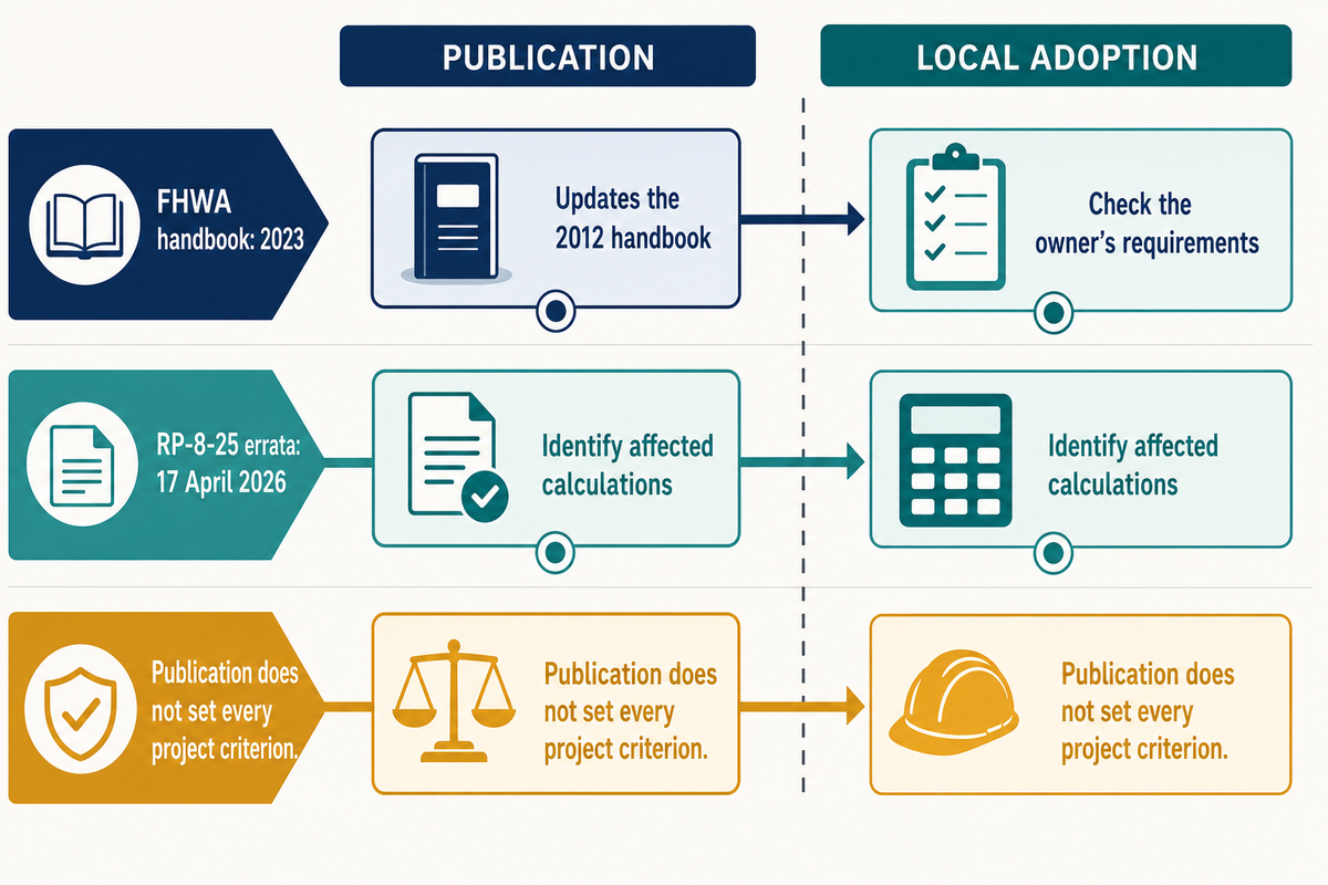
Recent roadway lighting publications make version control a practical design task. Evaluate the owner’s project requirements, publisher’s edition and errata before reusing a calculation template. New research may reveal trade-offs that an energy or brightness target misses, but new research doesn’t automatically set acceptance criteria.
The 2023 FHWA Lighting Handbook is an update to the 2012 publication. The formal abstract provided doesn’t describe a detailed design guide. Earlier FHWA chapters included here explain various principles; their historical numerical criteria shouldn’t be copied into current design documents without first reviewing the governing reference.
IES also published RP-8-25 errata dated 17 April 2026. Check the publisher’s errata before using a copied table or figure. A useful review note names the affected reference and states whether the calculation has been checked against it. Merely changing a report’s cover date doesn’t show that its inputs or criteria were reviewed.
A different concern is spectrum versus energy usage. In a 2024 modeled road-lighting study by Fryc and colleagues, in order to reduce skyglow potential, an energy trade off would occur based on the study assumptions and limitations. Does the proposed spectrum align with the required lighting outcome? Would using amber light sources in the design result in an increase of energy usage? The study does not establish that every amber product uses more energy, or that one colour temperature is best for every street.
Before approving a reused lighting plan for the next project, kindly request a short revision note from the vendor. The note must describe the difference between a publisher correction and a change in the owner’s brief, and identify any recalculations needed. When energy savings are claimed, review the same road geometry, visual task and operating schedule. An offer based on a different dimming state or omitted pedestrian area isn’t a like-for-like comparison.
Next step: acquire the surveyed drawing, owner-selected criteria and current quote, and use the two records above to identify missing decisions. Review commercial street light options with the above, or send the project requirements to Guangqi to request available model data.
Frequently asked questions
What are the recommended guidelines for street lighting design?
Street lighting guidelines should follow the owner’s specified references and the visual tasks on the site.
Start with the road authority’s brief, then identify the selected classes and evaluation methods. The submission should include the site geometry, matching luminaire files, maintenance assumptions and operating states. Use a lighting design guide to understand the method, but obtain the actual project criteria before selecting a numerical threshold. Keep the responsible reviewer identified on the submission.
Who is responsible for street lighting?
Street-light ownership, maintenance and design approval depend on the local asset and contract arrangements.
A municipality, road authority, utility or private owner may hold different responsibilities. Ask who owns the poles and luminaires, who maintains the equipment and who accepts design changes. Those roles need not belong to the same organisation. For a refurbishment, establish the boundaries before requesting quotations so the supplier knows which existing assets and service obligations are included.
What is the voltage for a street light?
Street-light voltage must match the site’s electrical design and the selected driver’s rated input.
There is no single supply voltage for every street-light installation. Request the actual supply details, driver input range and control interface, then have the electrical designer confirm compatibility and protection. A transformer or solar battery system introduces further design conditions. Neither the fixture’s wattage nor a photometric file confirms that the electrical supply is suitable for the installation.
Can lux be converted directly into road-surface luminance?
Lux and road-surface luminance have no universal fixed conversion factor.
The relationship needs pavement reflection and viewing assumptions. Ask for the specified quantity to be calculated directly. A lux plot cannot replace a required luminance assessment merely by changing the unit label.
Which street lighting design standards apply in the UK?
UK road-lighting briefs commonly reference British road-lighting guidance, with the applicable documents confirmed by the responsible authority.
BSI lists BS 5489-1:2020 for roads and public amenity areas. Its published scope excludes vehicular tunnels and underpasses. BSI’s PD CEN/TR 13201-1 summary describes class selection in relation to BS EN 13201-2. Confirm the editions and local requirements in the project brief. The public summaries explain scope; they do not provide every calculation rule or acceptance value. A supplier should identify the actual class-selection basis rather than claiming that a generic international file meets all UK requirements.
Are there secondary functions for light poles?
Light poles may carry additional equipment when the owner and relevant designers approve the arrangement.
A banner, sensor or camera can change the structural, access or electrical requirements. Show attachments on the drawings and review any obstruction of the lighting distribution separately from the pole’s primary lighting function.
When are street lighting design standards updated?
Road-lighting references are revised by their publishers; project adoption follows the owner’s applicable requirements.
Check the publisher’s current edition and corrections when preparing a new brief or reviewing an existing one. There is no single revision timetable shared by every organisation. For example, a new handbook, a revised recommended practice and a short errata sheet are different kinds of publication. Record which document the designer used and whether later corrections affect the calculation. Ask the approving party how an edition change should be handled under the project agreement. An updated catalogue entry alone does not demonstrate that an existing installation must immediately be redesigned.
Related reading for the project brief
How this road-lighting guide was prepared
This guide connects public road-lighting references with questions buyers can ask about a calculation and its matching product files. Standards catalogues establish scope and edition, while the worked records illustrate our editorial review method. No hypothetical layout is a Guangqi project result or a substitute for the responsible designer’s assessment. Published by Guangqi Lighting.
References & Sources
- IES: Lighting Roadway and Parking Facilities, RP-8-25+E2
- CIE 115:2010: road and pedestrian lighting
- FHWA 2012: lighting-system selection
- FHWA 2012: vision and glare
- FHWA: historical roadway lighting review
- FHWA: crosswalk visibility enhancements
- Fotios and Gibbons: road-lighting research review
- CIE 154:2003: outdoor lighting maintenance
- CIE 150:2017: obtrusive light
- FHWA 2023 Lighting Handbook: official abstract
- IES: RP-8-25 errata, 17 April 2026
- Fryc et al., 2024: modeled road-lighting tradeoffs
- BSI: BS 5489-1:2020 scope
- BSI: PD CEN/TR 13201-1 class-selection scope